This chapter describes how to use the SGI Management Center (SMC) for Altix ICE systems management software to discovery, install, and configure your Altix ICE system and covers the following topics:
| Note: If you are upgrading from a prior release or installing SMC for Altix ICE software patches, see “Installing SMC for Altix ICE Patches and Updating SGI Altix ICE Systems ”. |
This section describes what you should do if you wish to use the pre-installed software on the system admin controller (admin node).
You can use the cpasswd command to change the password on an already deployed system. You can use this command to change the global default password and per-node passwords with this command.
For a cpasswd usage statement, perform the following:
system-admin:~ # cpasswd --h
Usage:
  cpasswd [OPTION]...

Options:
      --debug              print debugging output
  -h, --help               print usage and exit
  -N, --node=NODE          change password for NODE
      --no-encrypt         do not encrypt the password, it is already encrypted
  -q, --quiet              only print errors
      --reset              reset to the current global password
      --stdin              read password from stdin
      --salt-id=ID         the salt id to use when encrypting

Details:
  If a node is specified with -N or --node, then that node will have
  a password that differs from the global password.  In order to
  remove a node-specific password, use --reset.

  Encrypting the password is done with the standard crypt(3) function,
  and therefore the salt ids supported are the same as specified in the
crypt(3) man page. The default is 1 (MD5). |
To configure the software that comes pre-installed on a SLES SMC for Altix ICE admin node, perform the following steps:
Use YaST to configure the first interface of the admin node for your house network. Settings to adjust may include the following:
Network settings including IP, default route, and so on
Time zone
If you need to adjust SGI Altix ICE settings, such as, any internal network ranges, modify the timezone, you will need to reset the database and rediscover the leader nodes and service nodes, as follows:
Start the configure-cluster command (see “configure-cluster Command Cluster Configuration Tool”).
Use configure-cluster to fix the networks.conf file and then the cadmin --set-subdomain command to change the sub-domain name.

Note: If you need to change the network ranges, modify the timezone, you need to choose the Reset Database operation. Read the on-screen instructions. After the database has been reset, choose Initial Setup Menu.
Choose Initial Setup Menu.
Start the options in this menu in order starting at Perform Initial Admin Node Infrastructure Setup. Note that if you are changing any network ranges or the cluster subdomain, you should choose Network Settings before proceeding to Perform Initial Admin Node Infrastructure Setup.

Note: You will get a message about the systemimager images already existing. You may choose to use the existing images instead of re-creating them. This will save about 30 minutes. Either choice is OK. Do not choose use existing images if you changed the root password or time zone as these settings are stored in the image when the image is created.
At this point, you can begin to discover leader and service nodes and continue cluster installation. See “discover Command”.
You can use the cpasswd command to change the password on an already deployed system. You can use this command to change the global default password and per-node passwords with this command.
For a cpasswd usage statement, perform the following:
system-admin:~ # cpasswd --h
Usage:
  cpasswd [OPTION]...

Options:
      --debug              print debugging output
  -h, --help               print usage and exit
  -N, --node=NODE          change password for NODE
      --no-encrypt         do not encrypt the password, it is already encrypted
  -q, --quiet              only print errors
      --reset              reset to the current global password
      --stdin              read password from stdin
      --salt-id=ID         the salt id to use when encrypting

Details:
  If a node is specified with -N or --node, then that node will have
  a password that differs from the global password.  In order to
  remove a node-specific password, use --reset.

  Encrypting the password is done with the standard crypt(3) function,
  and therefore the salt ids supported are the same as specified in the
crypt(3) man page. The default is 1 (MD5). |
To configure the software that comes pre-installed on a RHEL SMC for Altix ICE admin node, perform the following steps:
Configure the first interface (eth0) of the admin node for your house network. Settings to adjust may include the following:
Network settings including IP, default route, and so on
Time zone
If you need to adjust SGI Altix ICE settings, such as, any internal network ranges, modify the timezone, or change the system-wide root password, you will need to reset the database and rediscover the leader nodes and service nodes, as follows:
Start the configure-cluster command (see “configure-cluster Command Cluster Configuration Tool”).
Use configure-cluster to fix the networks.conf file and then the cadmin --set-subdomain command to change the sub-domain name.

Note: If you need to change the network ranges, modify the timezone, or change the system-wide root password, you need to choose the Reset Database operation. Read the on-screen instructions. After the database has been reset, choose Initial Setup Menu .
Choose Initial Setup Menu.
Start the options in this menu in order starting at Perform Initial Admin Node Infrastructure Setup. Note that if you are changing any network ranges or the cluster subdomain, you should choose Network Settings before proceeding to Perform Initial Admin Node Infrastructure Setup.

Note: You will get a message about the systemimager images already existing. You may choose to use the existing images instead of re-creating them. This will save about 30 minutes. Either choice is OK. Do not choose use existing images if you changed the root password or time zone as these settings are stored in the image when the image is created.
At this point, you can begin to discover leader and service nodes and continue cluster installation. See “discover Command”.
SGI Management Center (SMC) software running on the system admin controller (admin node) provides a robust graphical interface for system configuration, operation, and monitoring. For more information on using SMC, see SGI Management Center System Administrator's Guide .
This section describes two different methods you can use to access the SMC with SMC for Altix ICE 1.1 software.
You can install SMC using the SGI Admin Install DVD with SGI Management Center software bundle. In this method, SMC is automatically installed during infrastructure setup on the admin node (see “configure-cluster Command Cluster Configuration Tool”).
| Note: SMC requires an LK license. Save the license to /etc/lk/keys.dat . |
This section describes how to install the SGI Management Center (SMC) software on a system already running SMC for Altix ICE 1.1 software.
| Note: SMC requires an LK license. Save the license to /etc/lk/keys.dat . |
To install SGI Management Center (SMC) on a system running SMC for Altix ICE 1.1, perform the following steps:
Install and select the SMC repository with the crepo, as follows:
sys-admin:~ # crepo --add sgimc-1.2-cd1-media-sles11-x86_64.iso
sys-admin:~ #  crepo --select SGI-Management-Center-1.2-sles11
Start configure-cluster (see “configure-cluster Command Cluster Configuration Tool”) and run Install SGI Management Center (optional, if available). Quit configure-cluster when finished.

Note: This example applies to a SLES11 SP1 installation, RHEL 6 will be similar.
SMC requires an LK license. Save the license to /etc/lk/keys.dat.
Restart /etc/init.d/mgr, as follows:
sys-admin:~ # /etc/init.d/mgr restart
To run mgrclient, which will launch the SMC GUI, logout and log back in, to ensure that all environment variables are initialized appropriately.
This section provides a high-level overview of installing and configuring your SGI Altix ICE system.
To install and configure software on your SGI Altix ICE system, perform the following steps:
Follow “Installing SMC for Altix ICE Admin Node Software ” to install software on your system admin controller (admin node).
Follow “configure-cluster Command Cluster Configuration Tool” to configure the overall cluster.
Follow “Installing Software on the Rack Leader Controllers and Service Nodes” to install software on the leader nodes and service nodes.
Follow “Discovering Compute Nodes” to discover compute nodes.
Follow “Service Node Discovery, Installation, and Configuration” to discover, install and configure service nodes.
Ensure that all hardware components of the cluster have been discovered successfully, that is, admin, leader, service, and compute nodes and then follow “InfiniBand Configuration” to configure and check the status of the InfiniBand fabric.
Follow “Configuring the Service Node”, “Setting Up an NFS Home Server on a Service Node for Your Altix ICE System”, and “Setting Up a NIS Server for Your Altix ICE System” to complete your system setup.
This section describes how to install software on the system admin controller (admin node). The system admin controller contains software for provisioning, administering, and operating the SGI Altix ICE system. The SGI Admin Node Autoinstallation DVD contains a software image for the system admin controller (admin node) and contains SMC for Altix ICE and SGI Performance Suite packages, used in conjunction with the packages from the SLES11 DVD or RHEL 6 DVD to create leader, service, and compute images.
The root image for the admin node appliance is created by SGI and installed on to the admin node using the admin install DVD.
| Note: If you are reinstalling the admin node, you may want to make a backup of the cluster configuration snapshot that comes with your system so that you can recover it later. You can find it in the /opt/sgi/var/ivt directory on the admin node; it is the earliest snapshot taken. You can use this information with the interconnect verification tool (IVT) to verify that the current system shows the same hardware configuration as when it was shipped. For more information on IVT, see “Inventory Verification Tool” in Chapter 5. |
This section covers the following topics:
When using the configure-cluster command and adding the SLES media, only the first DVD is needed. The second SLES DVD, that contains the source RPMs, is not required for cluster operation and cannot be added to the repositories.
To install SLES 11 software images on the system admin controller, perform the following steps:
Turn on, reset, or reboot the system admin controller. The power on button is on the right of the system admin controller, as shown in Figure 2-1.
The serial console was always used even if the admin node install itself went to the VGA screen.
The new method configures the default serial console used by the system to match the console used for installation.
If you type "serial" at the Admin DVD install prompt, the system is also configured for serial console operations after installation and the yast2-firstboot questions appear on the serial console.
If you press Enter at the prompt or type vga, the VGA screen is used for installation, as previously, but also, the system is configured to use VGA as the default console, thereafter.
If you want to install to the VGA screen, but also want the serial console to be used for operations after initial installation, you should add a console= parameter to /boot/grub/menu.lst for each kernel line. This is done when the admin node boots for the first time after installation is completed. An example of this is, as follows:
kernel /boot/vmlinuz-2.6.16.46-0.12-smp root=/dev/disk/by-label/sgiroot  console=ttyS1,38400n8
splash=silent showopts
The appropriate entries were added to the inittab and /etc/security. The change, above, is the only one needed to switch the default console from VGA to serial. Likewise, to move from serial to VGA, simply remove the console= parameter, altogether.
Insert the SGI Admin Node Autoinstallation DVD in the DVD drive on the left of the system admin controller as shown in Figure 2-1.
An autoinstall message appears on your console, as follows:
SGI Admin Node Autoinstallation DVD

The first time you boot after installation, you will be prompted for
system setup questions early in the startup process.  These questions will
appear on the same console you use to install the system.

You may optionally append the "netinst" option with an nfs path to an ISO.

Cascading Dual-Boot Support:
install_slot=: install to a specific root slot, default 1
re_partition_with_slots=: re-partition with number of slot positions, up to 5.
default is 2. Reminder: applies to the whole cluster, not just admin node
destructive=1: allow slots with existing filesystems to be re-created
or signify ok to re-partition non-blank disks for re_partition_with_slots=

You may install from the vga screen or from the serial console.
The default system console will match the console you used for
installation. Type "vga" for the vga screen or "serial" for serial.
Append any additional parameters after "vga" or "serial".
EXAMPLE: vga re_partition_with_slots=3 netinst=server:/mntpoint/admin.iso

Note: If you want to use the serial console, enter serial at the boot: prompt, otherwise, output for the install procedure goes to VGA screen.
It is important to note that the command line arguments you supply to the boot prompt will have implications for your entire cluster including things such as how many root slots are available, and which root slot to install to. Please read “Cascading Dual-Boot” before you install the admin node so you are prepared for these crucial decisions.
You can hit the ENTER button at the boot prompt. The boot initrd.image executes, the hard drive is partitioned creating a swap area and a root file system, the Linux operating system and the cluster manager software is installed and a repository is set up for the rack leader controller, service node, and compute node software RPMs.

Note: When you boot the admin install DVD and choose to repartition an existing disk, all data is lost. If you are making use of cascading dual-boot (see “Cascading Dual-Boot”) and are reinstalling a given slot, the data in that slot will be deleted but the other slots will not be modified.
Once installation of software on the system admin controller is complete, remove the DVD from the DVD drive.
After the reboot completes, you will eventually see the YaST2 - firstboot@Linux Welcome screen, as shown in Figure 2-2. Select the Next button to continue.

Note: The YaST Installation Tool has a main menu with sub-menus. You will be redirected back to the main menu, at various times, as you follow the steps in this procedure.
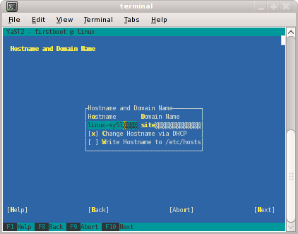
You will be prompted by YaST firstboot installer to enter your system details including the root password, network configuration, time zone, and so on.From the Hostname and Domain Name screen, as shown in Figure 2-3, enter the hostname and domain name of your system in the appropriate fields. Make sure that Change Hostname via DHCP is not selected (no x should appear in the box). Note that the hostname is saved to /etc/hosts in step 10, below. Click the Next button to continue.

Note: The mostly used keys are Tab and Shift + Tab to move forward and backward in modules, the arrow keys to move up and down or left and right in lists, the shortcuts (press Alt + highlighted letter) and Enter to execute the selected action or activate a menu item.
You can use Ctrl L to refresh the YaST screen as necessary.
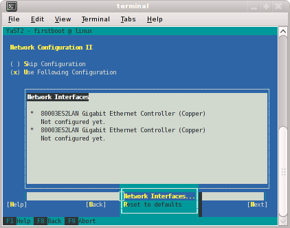
The Network Configuration II screen appears, as shown in Figure 2-4. Select Change and a small window pops up that lets you choose Network Interfaces... or Reset to Defaults. Choose Network Interfaces.
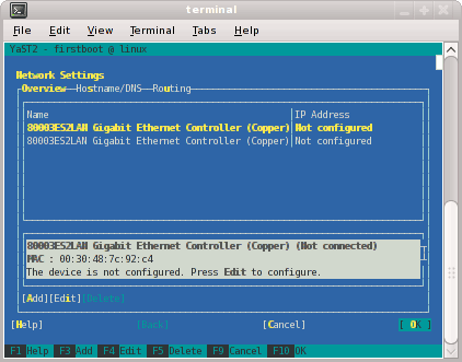
From the Network Settings screen, as shown in Figure 2-5, configure the first card under Name to establish the public network (sometimes called the house network) connection to your SGI Altix ICE system. To do this, highlight the first card and select Edit .

Note: In SLES11, this screen is also where we will come back to in order to set up things like the default route and DNS. You can see all of those menu choices just to the right of Overview in Figure 2-5.
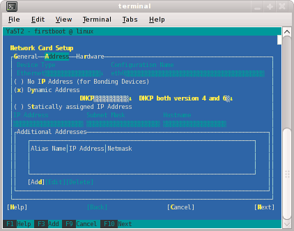
The Network Card Setup screen appears, as shown in Figure 2-6. SGI suggests using static IP addresses and not DHCP for admin nodes. Select Statically assigned IP Address. Once selected, you can enter the IP Address, Subnet Mask, and Hostname.

Note: You must use a fully qualified hostname (host + domain), such as, mysystem-admin.domainname .mycompany.com or the configure-cluster command will fail.
These are the settings for your admin node's house/public network interface. You will enter the default route, if needed, in a different step. Select Next to continue.
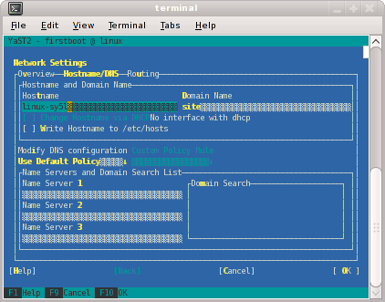
At this point, you are back at the Network Settings screen as shown in Figure 2-7. At this time, select Hostname/DNS. In this screen, you should enter your house/public network hostname and fully qualified domain names. In addition, any name servers for your house/public network should be supplied. Please select (ensure an x is in the box) for Write hostname to /etc/hosts. Do not select OK yet.
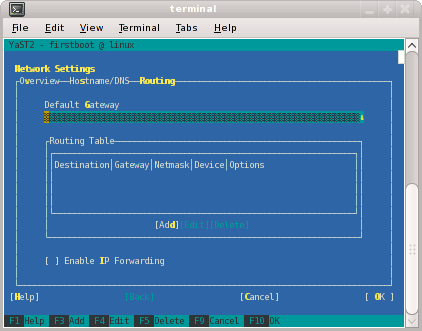
Select Routing shown in Figure 2-8 and enter your house/public network default router information there. Now you can select OK.
You are now back at the Network Configuration II screen, Click Next.
In the Clock and Time Zone screen, you can enter the appropriate details. Select Next to continue.
In the Password for the System Administrator "root"' screen, enter the password you wish to use. This password will be used throughout the cluster, not just the admin node. Select Next to continue.
In the User Authentication Method screen, most customers will want to stick with the default (Local). Select Next to continue.
In the New Local User screen, you can just select Next (and say Yes to the Empty User Login warning). Select Next to continue.
In Installation Completed, select Finish.
After you have completed the YaST first boot installation instructions, login into the system admin controller. You can use YaST to confirm or correct any configuration settings.

Note: It is important that you make sure that you network settings are correct before proceeding with cluster configuration You are now ready to run the configure-cluster command.
The configure-cluster command does not always draw the screen properly from the serial console. Therefore, log in to your admin node as root using ssh prior to running the configure-cluster command. For more information on the configure-cluster command, see “configure-cluster Command Cluster Configuration Tool”.
Use the configure-cluster command and RHEL media to install software on the admin node
To install RHEL 6 software images on the system admin controller, perform the following steps:
Turn on, reset, or reboot the system admin controller. The power on button is on the right of the system admin controller, as shown in Figure 2-1.
An autoinstall message appears on your console, as follows:
SGI Admin Node Autoinstallation DVD

The first time you boot after installation, you will be prompted for
system setup questions early in the startup process.  These questions will
appear on the same console you use to install the system.

You may optionally append the "netinst" option with an nfs path to an ISO.

Cascading Dual-Boot Support:
install_slot=: install to a specific root slot, default 1
re_partition_with_slots=: re-partition with number of slot positions, up to 5.
default is 2. Reminder: applies to the whole cluster, not just admin node
destructive=1: allow slots with existing filesystems to be re-created
or signify ok to re-partition non-blank disks for re_partition_with_slots=

You may install from the vga screen or from the serial console.
The default system console will match the console you used for
installation. Type "vga" for the vga screen or "serial" for serial.
Append any additional parameters after "vga" or "serial".
EXAMPLE: vga re_partition_with_slots=3 netinst=server:/mntpoint/admin.iso

Note: If you want to use the serial console, enter serial at the boot: prompt, otherwise, output for the install procedure goes to VGA screen.
It is important to note that the command line arguments you supply to the boot prompt will have implications for your entire cluster including things such as how many root slots are available, and which root slot to install to. Please read “Cascading Dual-Boot” before you install the admin node so you are prepared for these crucial decisions.
You can hit the ENTER button at the boot prompt. The boot initrd.image executes, the hard drive is partitioned creating a swap area and a root file system, the Linux operating system and the cluster manager software is installed and a repository is set up for the rack leader controller, service node, and compute node software RPMs.

Note: When you boot the admin install DVD and choose to repartition an existing disk, all data is lost. If you are making use of cascading dual-boot (see “Cascading Dual-Boot”) and are reinstalling a given slot, the data in that slot will be deleted but the other slots will not be modified.
Once installation of software on the system admin controller is complete, remove the DVD from the DVD drive.
Proceed to the next section (“Initial Configuration of a RHEL 6 Admin Node”), to configure RHEL 6 on the admin node.
This section describes how to configure Red Hat Enterprise Linux 6 on the system admin controller (admin node).
To perform the initial configuration of a RHEL6 Admin node, perform the following steps:
Add the IPADDR, NETMASK, and NETWORK values appropriate for the public (house) network interface to the /etc/sysconfig/network-scripts/ifcfg-eth0 file similar to the following example:
IPADDR=128.162.244.88
NETMASK=255.255.255.0
NETWORK=128.162.244.0
Create the /etc/sysconfig/network file similar to the following example:
[root@localhost ~]# cat /etc/sysconfig/network
NETWORKING=yes
HOSTNAME=my-system-admin
GATEWAY=128.162.244.1
Add the IP address of the house network interface and the name(s) of the admin node to /etc/hosts file similar to the following example:
# echo "128.162.244.88 my-system-admin.domain-name.mycompany.com my-system-admin" >> /etc/hosts
Set the admin node hostname, as follows:
# hostname my-system-admin
Configure the /etc/resolv.conf file with your DNS server set up. Later in the cluster set up process, these name servers will be used as the defaults for the House DNS Resolvers you configure in a later configure-cluster command step. Setting this now allows you to register with RHN and allows you to access your house network to access any DVD images or other settings you need. You may choose to defer this step, but then you will need to also defer rhn_register. Here is an example resolv.conf:
search mydomain.mycompany.com
nameserver 192.168.0.1
nameserver 192.168.0.25
Force the invalidation of the host cache of nscd with the nscd(8) command on the hosts file, as follows:
# nscd -i hosts
Restart the following services (in this order), as follows:
# /etc/init.d/network restart
# /etc/init.d/rpcbind start
# /etc/init.d/nfslock start
Set the local timezone. The timezone is set with /etc/localtime, a timezone definition file. The timezone defined in /etc/localtime can be determined, as follows:
# strings /etc/localtime | tail -1
CST6CDT,M3.2.0,M11.1.0
Link the appropriate timezone file from directory /usr/share/zoneinfo to /etc/localtime. For example, set timezone to Pacific Time / Los Angeles, as follows:
# /bin/cp -l /usr/share/zoneinfo/PST8PDT /etc/localtime.$$
# /bin/mv /etc/localtime.$$ /etc/localtime
Confirm the timezone, as follows:
# strings /etc/localtime | tail -1
PST8PDT,M3.2.0,M11.1.0
Set network time configuration.
On a RHEL6 admin node, the default ntp configuration file is replaced when the configure-cluster task Configure Time Client/Server (NTP) is run. Insert local ntp server information after running configure-cluster (see “Set Network Time Configuration for RHEL6 Admin Node”).
Make sure you have registered with the Red Hat Network (RHN). If you have not yet registered, run the following command:
% /usr/bin/rhn_register
Run the configure-cluster command. See “configure-cluster Command Cluster Configuration Tool”.
| Note: SGI suggests that you run the configure-cluster command either from the VGA screen or from an ssh session to the admin node. Avoid running the configure-cluster command from a serial console. |
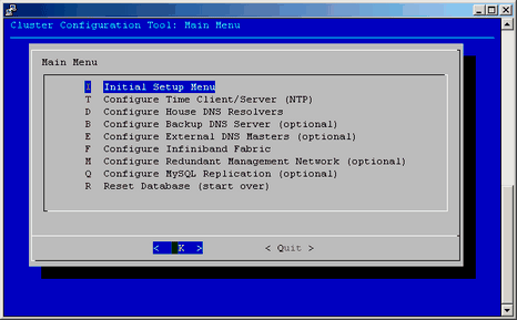
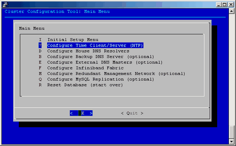
The configure-cluster command launches a cluster configuration tool as shown in Figure 2-9 on a previously configured machine. For information on initial configuration, see Procedure 2-8.
It allows you to perform the following:
Creates the root images for the service nodes, leader nodes, and compute blades
Prompts for installation media including SLES11 SP1 or RHEL 6 and optionally SGI Performance Suite software. The media is used to construct repositories that are used for software installation and updates.
Runs a set of commands that allows you to setup the cluster
Change the subnet numbers for the various cluster networks
Configure the subdomain of the cluster (which is likely different than the domain of eth0 on the system admin controller itself)
Configure the Backup DNS Server (see “Configure the Backup DNS Server”)
Configure the InfiniBand network (see “InfiniBand Configuration”)
Configure the Redundant Management network (see “Redundant Management Network”)
Information on using this tool is described in the procedure in the following section, see “Installing SMC for Altix ICE Admin Node Software ”.
This section describes how to use configure-cluster command to configure the system administrator controller (admin node) for your Altix ICE system.
To use the configure-cluster command to configure system admin controller (admin node), perform the following steps:
To start cluster configuration, enter the following command:
% /opt/sgi/sbin/configure-cluster
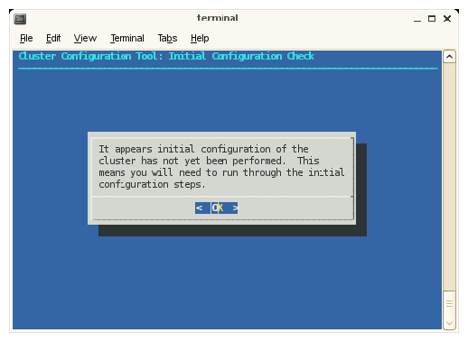
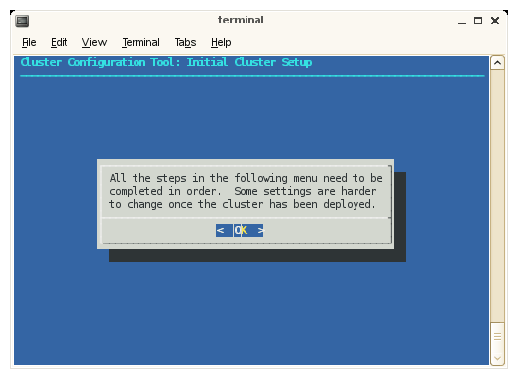
The Cluster Configuration Tool: Initial Configuration Check screen appears, as shown in Figure 2-10. This tool provides instructions on the steps you need to take to configure your cluster. Click OK to continue.
The Cluster Configuration Tool: Initial Cluster Setup screen appears, as shown in Figure 2-11. Read the notice and then click OK to continue.

Note: The Cluster Configuration Tool has a main menu with sub-menus. You will be redirected back to the main menu, at various times, as you follow the steps in this procedure.
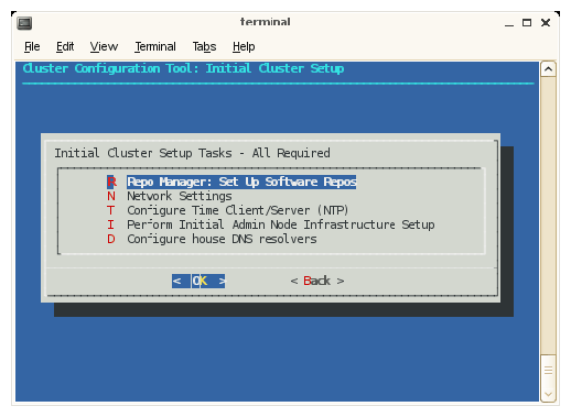
From the Initial Cluster Setup screen, select Repo Manager: Set up Software Repos and click OK.

Note: The next four screens use the crepo command to set up software repositories, such as, SGI Foundation, SMC for Altix ICE, SGI Performance Suite, SLES11 or RHEL 6. For more information, see “crepo Command” in Chapter 3. If you have licensed either the mpi or the accelerate software bundles from the SGI Performance Suite, now is the time to add them.
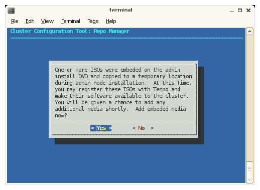
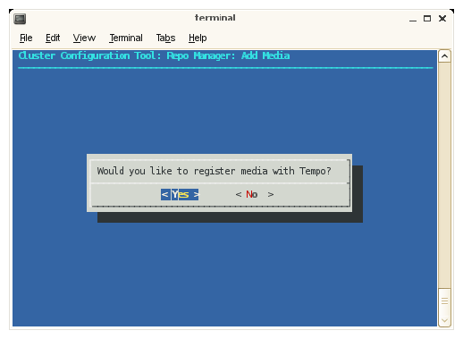
To register ISO images from the admin node with SMC for Altix ICE and make them available to your cluster, click the Yes button.
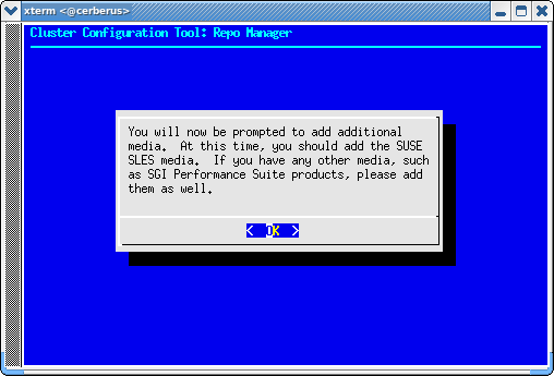
To add the SLES media and other media, such as, SGI Performance Suite, click OK.
To register additional media with SMC for Altix ICE, click Yes.
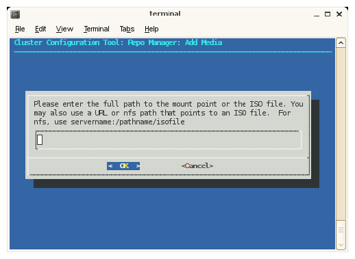
Enter the full path to the mount point or the ISO file or a URL or NFS path that points to an ISO file. Click OK to continue.
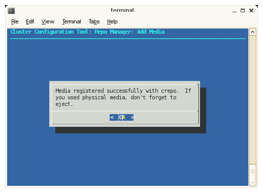
From the Repo Manager: Add Media screen, click OK to continue and eject you DVD if you used physical media.

Note: You will continue to be prompted to add additional media until you answer no. Once you answer no, you are directed back to the Inital Cluster Setup Tasks menu.
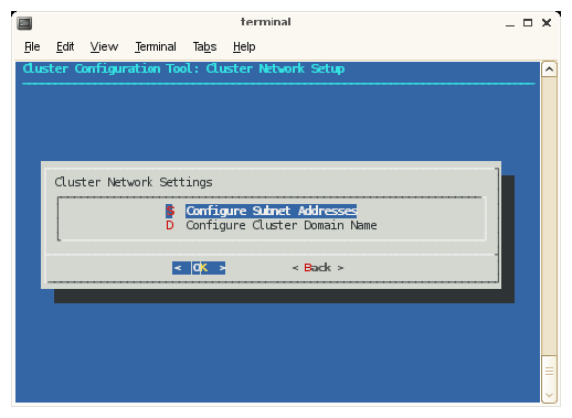
After choosing the Network Settings option, the Cluster Network Setup screen appears, as shown in Figure 2-18.
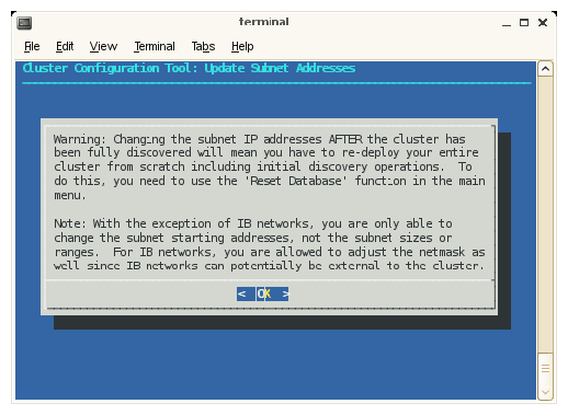
The subnet addresses allows you to change the cluster internal network addresses. SGI recommends that you do NOT change these. Click OK to continue to adjust subnets. Otherwise, select Domain Name: Configure Cluster Domain Name and then skip to step 31. A warning screen appears, as shown in Figure 2-19.
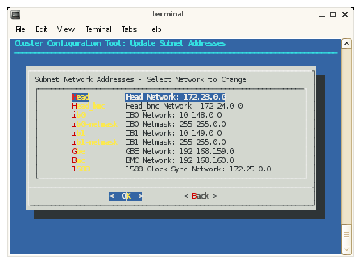
Once you deploy your Altix ICE system, to change the network IP values or change domain names, you must reset the system data base and then rediscover the system. You do not need to reinstall the admin node, however. Click OK to continue.The Update Subnet Addresses screen appears, as shown in Figure 2-20.
The default IP address of the system admin controller which is the Head Network for the Altix ICE system is shown. SGI recommends that you do NOT change the IP address of the system admin controller (admin node) or rack leader controllers (leader nodes) if at all possible. You can adjust the IP addresses of the InfiniBand network (ib0 and ib1) to match the IP requirements of the house network. Click OK to continue.
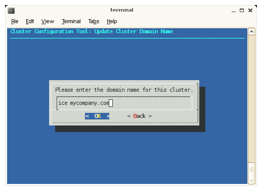
Enter the domain name for your Altix ICE system, as shown in Figure 2-21. Click OK to continue (this will be a subdomain to your house network, by default).
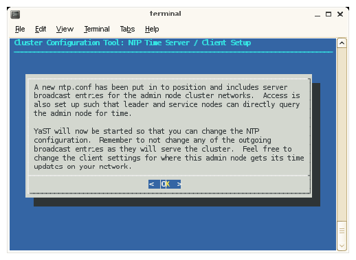
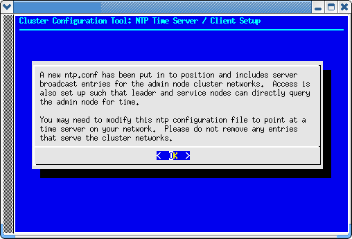
The configure-cluster NTP configuration screens with for RHEL 6 are different from those for SLES. The next operation in the Initial Cluster Setup menu is NTP Time Server/Client Setup is for SLES. This procedure changes your NTP configuration file. Click on OK to continue. This sets the system admin controller to serve time to the Altix ICE system and allows you to add time servers on your house networks, which you may optionally use.
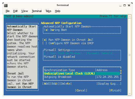
Configure NTP time service as shown in Figure 2-23. Click Next to continue.
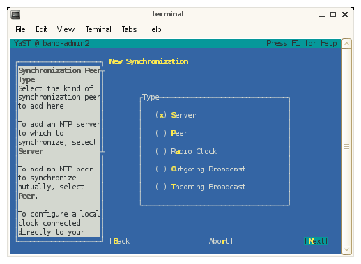
From the New Synchronization screen, select a synchronization peer and click Next to continue.
From the NTP Server screen, set the address of the NTP server and click OK to continue.
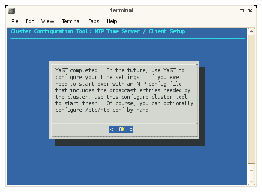
The YaST tool completes. Click OK to continue.
On a RHEL 6 installation, from the menu screen in which "set ntp servers" is selected, selecting setting ntp servers just displays Figure 2-27 and then returns you to the previous menu.
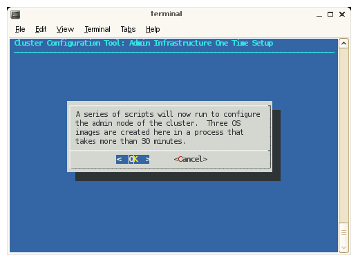
The next step in the Initial Cluster Setup menu directs you to select Perform Initial Admin Node Infrastructure Setup. This step runs a series of scripts that will configure the system admin controller of the Altix ICE system.
The script installs and configures your system and you should see an install-cluster completed line in the output.
The root images for the service, rack leader controller, and compute nodes are then created. The output of the mksiimage commands are stored in a log file at the following location:
/var/log/cinstallman
You can review the output if you so choose.
The final output of the script reads, as follows:
/opt/sgi/sbin/create-default-sgi-images Done!

Note: As it notes on the Admin Infrastructure One Time Setup screen, this step takes about 30 minutes.
Click OK to continue.
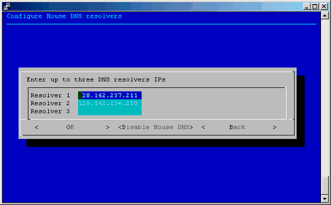
The next step in the Initial Cluster Setup menu is to configure the house DNS resolvers. It is OK to set these resolvers to the same name servers used on the system admin controller itself. Configuring these servers is what allows service nodes to resolve host names on your network. For a description of how to set up service nodes, see “Service Node Discovery, Installation, and Configuration”. This menu has default values printed that match your current admin node resolver setup. If this is ok, just select OK to continue. Otherwise, make any changes you wish to the resolver listing and select OK. If you do not wish to have any house resolvers, select Disable House DNS.
After entering the IPs, click OK to enable, click Disable House DNS to stop using house DNS resolution, click Back to leave house DNS resolution as it was when you started (disabled at installation).
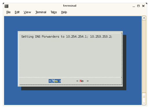
The setting DNS forwarding screen appears. Click Yes to continue.
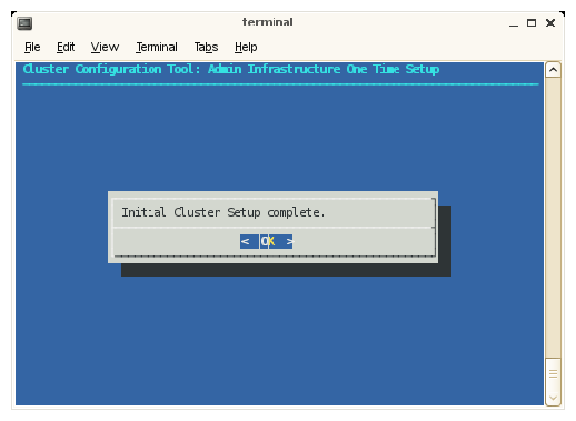
The Initial Cluster Setup complete message appears. Click OK to continue.
Proceed to “Installing Software on the Rack Leader Controllers and Service Nodes”. It describes the discovery process for the rack leader controllers in your system and how to install software on the rack leader controllers.

Note: The main menu contains a reset the database function that allows you to start software installation over without having to reinstall the system admin controller.
After finishing with the configure-cluster command, you probably will want to modify the ntp configuration to point at a time server on your network. Please do not remove entries that serve the cluster networks.
By default, the configuration in /etc/ntp.conf directs requests to public servers of the pool.ntp.org project.
server 0.rhel.pool.ntp.org server 1.rhel.pool.ntp.org server 2.rhel.pool.ntp.org |
To direct requests to the your company ntp server, for example ntp.mycompany.com, comment or delete the rhel.pool.ntp.org entries and insert the local entry, as follows:
# Use public servers from the pool.ntp.org project. # Please consider joining the pool (http://www.pool.ntp.org/join.html). #server 0.rhel.pool.ntp.org #server 1.rhel.pool.ntp.org #server 2.rhel.pool.ntp.org server ntp.mycompany.com |
Restart the ntp server, as follows:
# /etc/init.d/ntpd restart |
The discover command is used to discover rack leader controllers (leader nodes), service nodes, including their associated BMC controllers, in an entire system or in a set of one or more racks that you select. Rack numbers generally start at one. Service nodes generally start at zero. When you use the discover command to perform the discovery operation on your Altix ICE system, you will be prompted with instructions on how to proceed (see “Installing Software on the Rack Leader Controllers and Service Nodes”).
The operation of the discover command --delrack and --delservice options has changed. Now when using these options, the node is not removed completely from the database but it is marked with the administrative status NOT_EXIST. When you go to discover a node that previously existed, you now get the same IP allocations you had previously and the node is then marked with the administrative status of ONLINE. If you have a service node, for example, service0, that has a custom host name of "myhost" and you later go to delete service0 using the discover --delservice command, the host name associated with it will still be present. This can cause conflicts if you wish to reuse the custom host name " myhost" on a node other than service0 in the future. You can use the cadmin --db-purge --node service0 command that will remove the node entirely from the database (for more information, see “cadmin: SMC for Altix ICE Administrative Interface ” in Chapter 3). You can then reuse the “myhost” name.
There is a new hardware typed named generic. This hardware type has its MAC address discovered, but it is for devices that only have a single MAC address and do not need to be managed by SMC for Altix ICE software. The likely usage scenario is Ethernet switches that extend the management network that are necessary in large Altix ICE 8400 configurations.
When the generic hardware type is used for external management switches on large Altix ICE 8400 systems, the following guidelines should be followed:
The management switches should be the first things discovered in the system
The management switches should both start with their power cords unplugged (analogous to how SMC for Altix ICE discovers rack leader nodes and service nodes)
The external switches can be given higher numbered service numbered if your site does not want them to take lower numbers.
You can also elect to give these switches an alternate host name using the cadmin command after discovery is complete.
Examples of using the discover command generic hardware type are, as follows:
admin:~ # discover --service 98,generic
admin:~ # discover --service 99,generic
Note: When you use the discover command
to discover an SGI Altix XE500 service node, you must
specify the hardware type. Otherwise, the serial console will not be
set up properly. Use a command similar to the following:
|
For a discover command usage statement, perform the following:
admin ~# discover --h
Usage: discover [OPTION]...
Discover lead nodes, service nodes, and external switches.

Options:
  --delrack NUM                  mark rack leaders as deleted
  --delservice NUM               mark a service node as deleted
  --delswitch NAME               mark an external switch as deleted
  --force                        avoid sanity checks that require input
  --ignoremac MAC                ignore the specified MAC address
  --macfile FILE                 read mac addresses from FILE
  --rack NUM[,FLAG]...           discover a specific rack or set of racks
  --rackset NUM,COUNT[,FLAG]...  discover count racks starting at #
  --service NUM[,FLAG]...        discover the specified service node
  --switch NAME[,FLAG]...        discover the specified external switch
  --show-macfile                 print output usable for --macfile to stdout

Details:
  Any number of racks, service nodes, or external switches can be discovered
  in one command line.  Rack numbers generally start at 1, service nodes
  generally start at 0, and switches are named.  An existing node can be
  re-discovered by re-running the discover command.

  A comma searated set of optional FLAGs modify how discover proceeds for the
  associated node and sets it up for installation.  FLAGs can be used to
  specify hardware type, image, console device, etc.

  The 'generic' hardware type is for hardware that should be discovered but
  that only has one IP address associated with it.  SMC for Altix ICE will treat this
  hardware as an unmanaged service node.  An example use would be for the
  administrative interface of an ethernet switch being used for the SMC for Altix ICE
  management network. When this type is used, the generic hardware being
  discovered should be doing a DHCP request.

  The 'other' hardware type should be used for a service node which is not
  managed by SMC for Altix ICE.  This mode will allocate IPs for you and print them to
  the screen.  Since SMC for Altix ICE only prints IP addresses to the screen in this
  mode, the device being discovered does not even need to exist at the
  moment the operation is performed.

  The --macfile option can be used instead of discovering MACs by power cycling.
  All MACs to be discovered must be in the file.  External switches should
  simply repeat the same MAC twice in this file.  File format:
    <hostname> <bmc-mac> <host-mac>
  Example file contents:
    r1lead 00:11:22:33:44:55 66:77:88:99:EE:FF
    service0 00:00:00:00:00:0A 00:00:00:00:00:0B
    extsw1 00:00:00:00:00:11 00:00:00:00:00:11

Hardware Type Flags:
  altix4000 altix450 altix4700 default generic ice-csn iss3500-intel other uv10 xe210
  xe240 xe250 xe270 xe310 xe320 xe340 xe500

Switch Type Flags:
  default voltaire-isr-2004 voltaire-isr-2012 voltaire-isr-9024 voltaire-isr-9096
  voltaire-isr-9288

Other Flags:
  image=IMAGE                  specify an alternate image to install
  console_device=DEVICE        use DEVICE for console
  net=NET                      ib0 or ib1, for external IB switches only
  type=TYPE                    leaf or spine, for external IB switches only
  redundant_mgmt_network=YESNO yes or no, determines how network is configured
|
EXAMPLES
Example 2-1. discover Command Examples
The following examples walk you through some typical discover command operations.
To discover rack 1 and service node 0, perform the following:
admin:~ # /opt/sgi/sbin/discover --rack 1 --service0,xe210 |
In this example, service node 0 is an Altix XE210 system.
To discover racks 1-5, and service node 0-2, perform the following:
admin:~ # /opt/sgi/sbin/discover --rackset 1,5 --service0,xe240 --service 1,altix450 --service 2,other |
In this example, service node 1 is an Altix 450 system. Service node 2 is other hardware type.
To discover service 0, but use service-myimage instead of service-sles11 (default), perform the following:
admin:~ # /opt/sgi/sbin/discover --service0,image=service-myimage |
| Note: You may direct a service node to image itself with a custom image later, without re-discovering it. See “cinstallman Command” in Chapter 3. |
To discover racks 1 and 4, service node 1, and ignore MAC address 00:04:23:d6:03:1c , perform the following:
admin:~ # /opt/sgi/sbin/discover --ignoremac 00:04:23:d6:03:1c --rack 1 --rack 4 --service0 |
The discover command supports external switches in a manner similar to racks and service nodes, except that switches do not have BMCs and there is no software to install. The syntax to add a switch is, as follows:
admin:~ # discover --switch name,hardware,net=fabric,type=spine |
where name can be any alphanumeric string, hardware is any one of the supported switch types (run discover --help to get a list), and net= fabric is either ib0 or ib1 , and type= is leaf or spine, for external IB switches only.
An example command is, as follows:
# discover --switch extsw,voltaire-isr-9024,net=ib0,type=spine |
Once discover has assigned an IP address to the switch, it will call the fabric management sgifmcli command to initialize it with the information provided. The /etc/hosts and /etc/dhcpd.conf files should also have entries for the switch as named, above. You can use the cnodes --switch command to list all such nodes in the cluster.
To remove a switch, perform the following:
admin:~ # discover --delswitch name |
where name is that of a previously discovered switch.
An example command is, as follows:
admin:~ # discover --delswitch extsw |
When your are discovering a node, you can use an additional option to turn on or off the redundant management network for that node. For example:
admin:~ # discover --service0,xe500,redundant_mgmt_network=no |
Discover a switch used to extend the SMC for Altix ICE management network, a generic device, as follows:
admin:~ # discover --service 99,generic |
The discover command, described in “discover Command”, sets up the leader and managed service nodes for installation and discovery. This section describes the discovery process you use to determine the Media Access Control (MAC) address, that is, the unique hardware address, of each rack leader controller (leader nodes) and then how to install software on the rack leader controllers.
| Note: When leader and service nodes come up and are configured to install
themselves, they determine which Ethernet devices are the integrated ones
by only accepting DHCP leases from SMC for Altix ICE. They then know that
the interface they got a lease from must be an integrated Ethernet device.
This is facilitated by using a DHCP option code. SMC for Altix ICE uses
option code 149 by default. In rare situations, a house network DHCP
server could be configured to use this option code. In that case, nodes
that are connected to the house network could misinterpret a house DHCP
server as being a SMC for Altix ICE one and auto detect the interface
incorrectly. This would lead to an installation failure.
To change the dhcp option code number used for this operation, see the cadmin --set-dhcp-option option. The --show-dhcp-option will show the current value. For more information on the using the cadmin command, see “cadmin: SMC for Altix ICE Administrative Interface ” in Chapter 3. |
To install software on the rack leader controllers, perform the following steps:
Use the discover command from the command line, as follows:
# /opt/sgi/sbin/discover --rack 1

Note: You can discover multiple racks at a time using the --rackset option. Service nodes can be discovered with the --service option.
The discover script executes. When prompted, turn the power on to the node being discovered and only that node.

Note: Make sure you only power on the node being discovered and nothing else in the system. Make sure not to power the system up itself.
When the node has electrical power, the BMC starts up even though the system is not powered on. The BMC does a network DHCP request that the discover script intercepts and then configures the cluster database and DHCP with the MAC address for the BMC. The BMC then retrieves its IP address. Next, this script instructs the BMC to power up the node. The node performs a DHCP request that the script intercepts and then configures the cluster database and DHCP with the MAC address for the node. The rack leader controller installs itself using the systemimager software and then boots itself.
The discover script will turn on the chassis identify light for 2 minutes. Output similar to the following appears on the console:
Discover of rack1 / leader node r1lead complete
r1lead has been set up to install itself using systemimager
The chassis identify light has been turned on for 2 minutes
The blue chassis identify light is your cue to power on the next rack leader controller and start the process all over.
You may watch install progress by using the console command. For example, console r1lead connects you to the console of the r1lead so that you can watch installation progress. The sessions are also logged. For more information on the console command, see “Console Management” in Chapter 3.
Using the identify light, you can configure all the rack leader controllers and service nodes in the cluster without having to go back and fourth to and from your workstation between each discovery operation. Just use the identify light on the node that was just discovered as your cue to move to the next node to plug in.
Shortly after the discover command reports that discovery is complete for a given node, that node installs itself. If you supplied multiple nodes on the discover command line, it is possible multiple nodes could be in different stages of the imaging/installation process at the same time. For rack leaders, when the leader boots up for the first time, one process it starts is the blademond process. This process discovers the IRUs and attached blades and sets them up for use. The blademond process is described in “blademond Command For Automatic Blade Discovery ”, including which files to watch for progress.
If your discover process does not find the appropriate BMC after a few minutes, the following message appears:
==============================================================================
Warning: Trouble discovering the BMC!
==============================================================================
3 minutes have passed and we still can't find the BMC we're looking for.
We're going to keep looking until/if you hit ctrl-c.

Here are some ideas for what might cause this:

  - Ensure the system is really plugged in and is connected to the network.
  - This can happen if you start discover AFTER plugging in the system.
    Discover works by watching for the DHCP request that the BMC on the system
    makes when power is applied.  Only nodes that have already been discovered
    should be plugged in.  You should only plug in service and leader nodes
    when instructed.
  - Ensure the CMC is operational and passing network traffic.
  - Ensure the CMC firwmare up to date and that it's configured to do VLANs.
  - Ensure the BMC is properly configured to use dhcp when plugged in to power.
  - Ensure the BMC, frusdr, and bios firmware up to date on the node.
  - Ensure the node is connected to the correct CMC port.

Still Waiting.   Hit ctrl-c to abort this process.  That will abort discovery
at this problem point -- previously discovered components will not be affected.
==============================================================================
If your discover process finds the appropriate BMC, but cannot find the leader or service node that is powered up after a few minutes, the following message appears:
==============================================================================
Warning: Trouble discovering the NODE!
==============================================================================
4 minutes have passed and we still can't find the node.
We're going to keep looking until/if you hit ctrl-c.

If you got this far, it means we did detect the BMC earlier,
but we never saw the node itself perform a DHCP request.

Here are some ideas for what might cause this:

 - Ensure the BIOS boot order is configured to boot from the network first
 - Ensure the BIOS / frusdr / bmc firmware are up to date.
 - Is the node failing to power up properly? (possible hardware problem?)
   Consider manually pressing the front-panel power button on this node just
   in case the ipmitool command this script issued failed.
 - Try connecting a vga screen/keyboard to the node to see where it's at.
 - Is there a fault on the node?  Record the error state of the 4 LEDs on the
   back and contact SGI support.  Consider moving to the next rack in the mean
   time, skippnig this rack (hit ctrl-c and re-run discover for the other
   racks and service nodes).

Still Waiting.   Hit ctrl-c to abort this process.  That will abort discovery
at this problem point -- previously discovered components will not be affected.
==============================================================================
You are now ready to discover and install software on the compute blades in the rack. For instructions, see “Discovering Compute Nodes”.
You no longer need to explicitly call the discover-rack command to discover a rack and integrate new blades. This is done automatically by a the blademond daemon that runs on the leader nodes.
The blademond daemon is started up when the leader node boots after imaging and begins to poll the chassis management control (CMC) blade in each IRU to determine if any new blades are present. It polls the CMCs every two minutes to see if anything has changed. If something has changed (a new blade, a blade removed, or a blade swapped), it sends the new slot map to the admin node and calls the discover-rack command to integrate the changes. It then boots new nodes on the default compute image.
The blademond daemon maintains its log file at /var/log/blademond on the leader nodes.
You can turn on debug mode in the blademond daemon by sending it a SIGUSR1 signal from the leader node, as follows:
# kill -USR1 pid |
To turn debug mode off, send it another SIGUSR1 signal. You should see a message in the blademond log about debug mode being enabled or disabled.
The blademond daemon maintains the slot map at /var/opt/sgi/lib/blademond/slot_map on the leader nodes. This appears as /var/opt/sgi/lib/blademond/slot_map. rack_number on the admin node.
This section describes how to discover compute nodes in your Altix ICE system.
| Note: You no longer need to explicitly call the discover-rack command to discover a rack and integrate new compute nodes (blades). This is done automatically by the blademond daemon that runs on the leader nodes (see “blademond Command For Automatic Blade Discovery ”). |
To discover compute nodes (blades) in your Altix ICE system, perform the following:
Complete the steps in “Installing Software on the Rack Leader Controllers and Service Nodes”.
For instructions on how to configure, start, verify, or stop the InfiniBand Fabric management software on your Altix ICE system, see Chapter 4, “System Fabric Management”.
| Note: The InfiniBand fabric does not automatically configure itself. For information on how to configure and start up the InfiniBand fabric, see Chapter 4, “System Fabric Management”. |
Service nodes are discovered and deployed similar to rack leader controllers (leader nodes). The discover command, with the --service related commands, allow you to discover service nodes in the same discover operation that discovered the leader nodes.
Like rack leader controllers, the service node is automatically installed. The service node image associated with the given service node is used for installation.
Service nodes have one (or possibly two, see “Redundant Management Network”) Ethernet connection(s) to the Altix ICE network. Service nodes may also be connected to your house network. Typically, interfaces with lower numbers are connected to the Altix ICE network (for example, eth0, or eth0 and eth1), and any remaining network interfaces are used to connect to the house network.
The firstboot system setup script does not start automatically on the system console after the first boot after installation (unlike the admin node).
Use YAST to set up the public/house network connection on the service node, as follows:
Select the interface which is connected to your house network to configure in firstboot (for example, eth1 or eth2).
If you change the default host name, you need to make sure that the cluster service name is still resolvable as tools depend on that.
Name service configuration is handled by the admin and leader nodes. Therefore, service node resolv.conf files need to always point to the admin and leader nodes in order to resolve cluster names. If you wish to resolve host names on your "house" network, use the configure-cluster command to configure the house name servers. The admin and leader nodes will then be able to resolve your house network addresses, in addition to the internal cluster hostnames. Besides, the cluster configuration update framework may replace your resolv.conf file anyway when cluster configuration adjustments are made.
Do not change resolv.conf and do not configure different name servers in yast.
In some rare cases, it is possible that your house networks uses the the same DHCP option identifier as the SMC for Altix ICE systems software. In this case, two events could happen:
The imaging client could get a DHCP lease from the your house network DHCP server.
Imaging could fail because it cannot reach the admin node.
The SMC for Altix ICE DHCP option identifier is 149, as shown by the cadmin command:
admin:~ # cadmin --show-dhcp-option 149 |
You can use the cadmin --set-dhcp-option {value} option, to change the SMC for Altix ICE DHCP option identifier so it is different from your house network. For more information on the cadmin command, see “cadmin: SMC for Altix ICE Administrative Interface ” in Chapter 3.
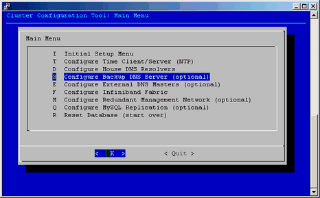
When this feature is configured, the compute nodes are able to use a service node as a secondary DNS server. If the rack leader goes down, the compute nodes running tmpfs will switch to use the service nodes as DNS server allowing them to function properly while the rack leader is being serviced. You can use the Configure Backup DNS Server option on the Cluster Configuration Tool: Main Menu to configure the backup DNS server, as shown in Figure 2-32.
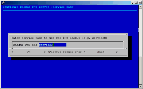
Enter the service node that you want to use for DNS backup server, for example service0, and click on OK, as shown in Figure 2-33.
If you want to disable this feature, just select Disable Backup DNS from the same menu and confirm that Yes you have selected to disable DNS backup.
You can also use the /opt/sgi/sbin/backup-dns-setup utility to enable or disable the DNS backup, as follows:
# backup-dns-setup usage: /opt/sgi/sbin/backup-dns-setup [--set-backup | --delete-backup | --distribute-config | --show-backup] # backup-dns-setup --show-backup service0 # backup-dns-setup --delete-backup Shutting down name server BIND done sys-admin: update-configs: updating SMC for Altix ICE configuration files sys-admin: update-configs: -> dns ... # backup-dns-setup --set-backup service0 Shutting down name server BIND waiting for named to shut down (29s) done sys-admin: update-configs: updating SMC for Altix ICE configuration files sys-admin: update-configs: -> dns ... |
Before you start configuring the InfiniBand network, you need to ensure that all hardware components of the cluster have been discovered successfully, that is, admin, leader, service and compute nodes. You also need to be finished with the cluster configuration steps in “configure-cluster Command Cluster Configuration Tool”.
Sometimes, InfiniBand switch monitoring errors can appear, before the InfiniBand network has been fully configured. To disable InfiniBand switch monitoring, perform the following command:
% cattr set disableIbSwitchMonitoring true |
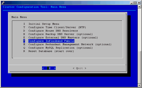
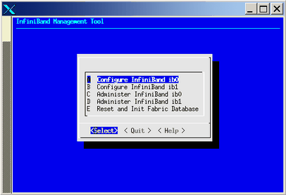
To configure the InfiniBand network, start the configure-cluster command again on the admin node. Since the Initial Setup has been done already, you can now use the Configure InfiniBand Fabric option to configure the InfiniBand fabric as shown in Figure 2-34.
Select the Configure InfiniBand Fabric option, the InfiniBand Fabric Management tool appears, as shown in Figure 2-35.
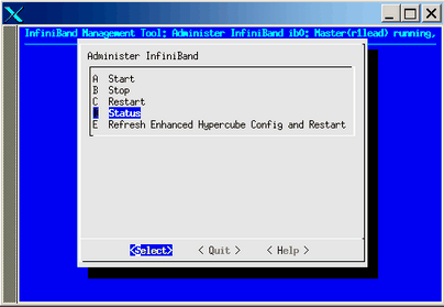
Use the the online help available with this tool to guide you through the InfiniBand configuration. After configuring and bringing up the InfiniBand network, select the Administer InfiniBand ib0 option or the Administer InfiniBand ib1 option, the Administer InfiniBand screen appears as shown in Figure 2-36. Verify the status using the Status option.
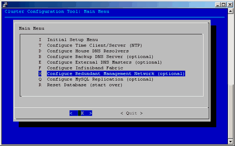
This section describes how to configure the redundant management network. For the SGI Altix ICE 8400 series systems, when system nodes are discovered for the first time, the redundant management network value is turned on. On is the default value. For systems lacking a redundant ethernet interface, such as, the SGI Altix ICE 8200 series systems, the redundant management network support is off by default. You can use the Configure Redundant Management Network option on the Cluster Configuration Tool: Main Menu to configure the redundant management network, as shown in Figure 2-37.
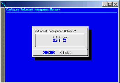
Select the option and turn off or turn on the redundant network management value, as shown in Figure 2-38.
Each node has the redundant network management either turned on or off. The redundant management network feature is on, by default, if the admin node has an eth2 interface and off, by default, if the admin lacks eth2. The first time the configure-cluster command runs, it sets the admin node's value to the same as the global value. Additional executions of configure-cluster command will not set the admin nodes value.
When your are discovering a node, you can use an additional option to turn on or off the redundant management network for that node. For example:
# discover --service0,xe500,redundant_mgmt_network=no |
This turns the value of redundant_mgmt_network to no (off) for service0. Valid values are yes and no.
Later, you can use the cadmin to change the redundant_mgmt_network value on or off, as follows:
# cadmin --set-redundant-mgmt-network --node service0 yes |
# cadmin --set-redundant-mgmt-network --node service0 no |
Example 2-2. Turning On the Redundant Management Network On Leader Node
To turn on the redundant managment network on a rack leader controller (leader node), perform the following command:
# cadmin --set-redundant-mgmt-network --node r1lead yes r1lead should now be rebooted. |
The cadmin command returns a message to reboot the r1lead node.
To reboot the node, perform the following command:
# cpower --reboot r1lead |
Replication in MySQL enables data from the master MySQL database server (admin node) to be replicated to one or more MySQL database slaves (leader and service nodes).
If your site has a large number of racks, using this feature can reduce the amount of contention for database resources on the admin node.
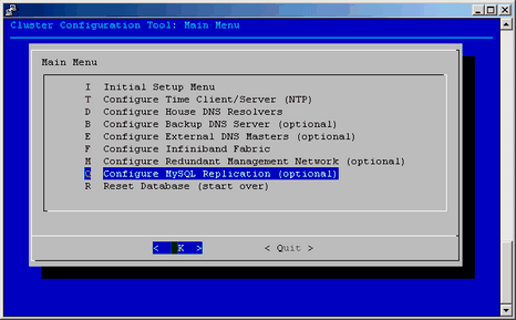
Replication is enabled by default. From the Cluster Configuration Tool: Main Menu (launched by the configure-cluster command), select Configure MySQL Replication (optional) , as shown in Figure 2-39.
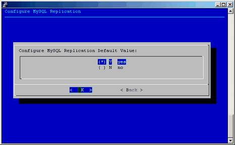
Select the yes on the Configure MySQL Replication screen, as shown in Figure 2-40, and press OK to enable MySQL replication. Press no to disable this feature.
When enabling or disabling this feature, the configure-cluster command will back up the database, save some system attributes, and call /etc/opt/sgi/conf.d/80-update-mysql on the admin node, leader nodes, and service nodes.
When replication is OFF and the cattr command is run by a script on a leader or service node, it uses the database on the admin node. You can verify this, as follows:
r1lead:~ # chkconfig -l mysql
    mysql                     0:off  1:off  2:off   3:off   4:off  5:off   6:off
r1lead:~ # grep -e hostname /etc/opt/sgi/cattr.conf
    hostname = admin
r1lead:~ # cattr list | grep my_sql_replication
    my_sql_replication      : no
|
When replication is ON and cattr is run by a script on a leader or service node, it uses the replicated database on the node itself. You can verify this, as follows:
r1lead:~ # chkconfig -l mysql mysql 0:off 1:off 2:on 3:on 4:off 5:on 6:off r1lead:~ # grep -e hostname /etc/opt/sgi/cattr.conf hostname = localhost r1lead:~ # cattr list | grep my_sql_replication my_sql_replication : yes |
See Chapter 15 of the MySQL 5.0 Reference Manual for detailed information regarding how replication is implemented and configured. This manual is available at http://dev.mysql.com/doc/refman/5.0/en/replication.html.
This section describes how to configure a service node and covers the following topics:
You may want to reach network services outside of your SGI Altix ICE system. For this type of access, SGI recommends using Network Address Translation (NAT), also known as IP Masquerading or Network Masquerading. Depending on the amount of network traffic and your site needs, you may want to have multiple service nodes providing NAT services.
To enable NAT on your service node, perform the following steps:
Use the configuration tools provided on your service node to turn on IP forwarding and enable NAT/IP MASQUERADE.
Specific instructions should be available in the third-party documentation provided for your storage node system. Additional documentation is available at /opt/sgi/docs/setting-up-NAT/README. This document describes how to get NAT working for both IB interfaces.

Note: This file is only on the service node. You need to # ssh service0 and then from service0 # cd /opt/sgi/docs/setting-up-NAT .
Update the all of the compute node images with default route configured for NAT.
SGI recommends a script on the system admin controller at /opt/sgi/share/per_host_customization/global/sgi-static-routes that can customize the routes based upon rack, IRU, and slot of the compute blade. Some examples are available in that script.
Use the cimage --push-rack command to propagate the changes to the proper location for compute nodes to boot. For more information on using the cimage command, see “cimage Command” in Chapter 3 and “Customizing Software On Your SGI Altix ICE System” in Chapter 3.
Use the cimage --set command to select the image.
Reboot/reset the compute nodes using that desired image.
Once the service node(s) has NAT enabled, is attached to an operational house network, and the compute nodes are booted from an image which sets their routing to point at the service node, test the NAT operation by using the ping(8) command to ping known IP addresses on the house network from an interactive session on the compute blade.
See the troubleshooting discussion that follows.
Troubleshooting can become very complex. The first steps are to determine that the service node(s) are correctly configured for the house network and can ping the house IP addresses. Good choices are house name servers possibly found in the /etc/resolv.conf or /etc/name.d.conf files on the admin node. Additionally, the default gateway addresses for the service node may be a good choice. You can use the netstat -rn command for this information, as follows:
system-1:/ # netstat -rn Kernel IP routing table Destination Gateway Genmask Flags MSS Window irtt Iface 128.162.244.0 0.0.0.0 255.255.255.0 U 0 0 0 eth0 172.16.0.0 0.0.0.0 255.255.0.0 U 0 0 0 eth1 169.254.0.0 0.0.0.0 255.255.0.0 U 0 0 0 eth0 172.17.0.0 0.0.0.0 255.255.0.0 U 0 0 0 eth1 127.0.0.0 0.0.0.0 255.0.0.0 U 0 0 0 lo 0.0.0.0 128.162.244.1 0.0.0.0 UG 0 0 0 eth0 |
If the ping command executed from the service node to the selected IP address gets responses, network monitoring tools such as tcpdump(1) should be used. On the service node, monitor the eth1 interface and simultaneously in a separate session monitor the ib[01] interface. You should specify monitoring specific-enough to not have additional noise then attempt execute a ping command from the compute node.
Example 2-3. tcpdump Command Examples
tcpdump -i eth1 ip proto ICMP # Dump ping packets on the public side of service node. tcpdump -i ib1 ip proto ICMP # Dump ping packets on the IB fabric side of service node. tcpdump -i eth1 port nfs # Dump NFS traffic on the eth1 side of service node. tcpdump -i ib1 port nfs # Dump NFS traffic on the eth1 side of service node. |
If packets do not reach the service nodes respective IB interface, perform the following:
Check the system admin controller's compute image configuration of the default route.
Verify that this image has been pushed to the compute nodes.
Verify that the compute nodes have booted with this image.
If the packets reach the service nodes IB interface, but do not exit the eth1 interface, verify the NAT configuration on the service node.
If the packets exit the eth1 interface, but replies do not return, verify the house network configuration and that IP masquerading is properly configured so that the packets exiting the interface appear to be originating from the service node and not the compute node.
You may want to configure service node(s) to act as NAT gateways for your cluster (see “Service Node Configuration for NAT”) and to have the host names for the compute nodes in the cluster resolve through external DNS servers.
You need to reserve a large block of IP addresses on your house network. If you configure to resolve via external DNS, you need to do it for both the ib0 and ib1 networks, for all node types. In other words, ALL -ib* addresses need to be provided by external DNS. This includes compute nodes, leader nodes, and service nodes. Careful planning is required to use this feature. Allocation of IP addresses will often require assistance from a network administrator of your site.
Once the IP addresses have been allocated on the house network, you need to tell the SMC for Altix ICE software the IP addresses of the DNS servers on the house network that the SMC for Altix ICE software can query for hostname resolution.
To do this, use the configure-cluster tool (see “configure-cluster Command Cluster Configuration Tool”). The menu item that handles this operation is Configure External DNS Masters (optional).
Some important considerations are, as follows:
It is important to note that if you choose to use external DNS, you need to make this change before discovering anything. The change is not retroactive. If you have already discovered some nodes, then turn on external DNS support, the IP addresses assigned by SMC for Altix ICE for the nodes already discovered will remain.
This is an optional feature that only a small set of customers will need to use. It should not be used by default.
This feature only makes sense if the compute nodes can reach the house network. This is not the default case for SGI Altix ICE systems.
It is assumed that you have already configured a service node to act as a NAT gateway to your house network (see “Service Node Configuration for NAT”) and that the compute nodes have been configured to use that service node as their gateway.
For information on setting up DNS, see Figure 2-29.
Assuming the installation has either NAT or Gateway operations configured on one or more service nodes, the compute nodes can directly mount the house NFS server's exports (see the exports(5) man page).
To allow the compute nodes to directly mount the house NFS server's exports, perform the following steps:
Edit the system admin controller's /opt/sgi/share/per_host_customization/global/sgi-fstab file or alternatively an image-specific script.
Add the mount point, push the image, and reset the node.
The server's export should get mounted. If it is not, use the technique for troubleshooting outlined in “Troubleshooting Service Node Configuration for NAT”.
This section describes two different ways to configure NIS for service nodes and compute blades when you want to use the house network NIS server, as follows:
NIS with the compute nodes directly accessing the house NIS infrastructure
NIS with a service node as a NIS slave server to the house NIS master
The first approach would be used in the case where a service node is configured with network address translation (NAT) or gateway operations so that the compute nodes can access the house network directly.
The second approach may be used if the compute nodes do not have direct access to the house network.
To setup NIS with the compute nodes directly accessing the house NIS infrastructure, perform the following steps:
In this case, you do not have to set up any additional NIS servers. Instead, each service node and compute node should be configured to bind to the existing house network servers. The nodes should already have the ypbind package installed. The following steps should work with most Linux distributions. You may need to vary them slightly to meet your specific needs.
For service nodes, the instructions are very similar to those found in “Setting Up a SLES Service Node as a NIS Client”.
The only difference is that you should configure yp.conf to look at the IP address of your house network NIS server and not the leader node as is described in the sections listed, above.
To setup NIS with a service node as a NIS slave server to the house NIS master, perform the following:
Any service nodes that are NOT acting as an NIS slave server can be pointed at the existing house network NIS servers as described in Procedure 2-13. This is because they have house interfaces.
One (or more) service node(s) should be then be configured as NIS slave server(s) to the existing house network NIS Master server.
Since SGI can not anticipate what operating system or release the house network NIS Master server is running, no suggestions on any configuration you need to do to tell it that you are adding new NIS slave servers can be offered.
These section describes how to make a service node an NFS home directory server for the compute nodes.
| Note: Having a single, small server provide filesystems to the whole Altix ICE system could create network bottlenecks that the hierarchical design of Altix ICE is meant to avoid, especially if large files are stored there. Consider putting your home filesystems on an NAS file server. For instructions on how to do this, see “Service Node Configuration for NFS ”. |
The instructions in this section assume you are using the service node image provided with the SMC for Altix ICE software. If you are using your own installation procedures or a different operating system, the instructions will not be exact but the approach is still appropriate.
| Note: The example below specifically avoids using /dev/sdX style device names. This is because /dev/sdX device names are not persistent and may change as you adjust disks and RAID volumes in your system. In some situations, you may assume /dev/sda is the system disk and that /dev/sdb is a data disk; this is not always the case. To avoid accidental destruction of your root disk, follow the instructions given below. |
When you are choosing a disk, please consider the following:
To pick a disk device, first find the device that is being currently used as root. Avoid re-partitioning the installation disk by accident. To find which device is being used for root, use this command:
# ls -l /dev/disk/by-label/sgiroot lrwxrwxrwx 1 root root 10 2008-03-18 04:27 /dev/disk/by-label/sgiroot -> ../../sda2 |
At this point, you know the sd name for your root device is sda.
SGI suggests you use by-id device names for your data disk. Therefore, you need to find the by-id name that is NOT your root disk. To do that, use ls command to list the contents of /dev/disk/by-id, as follows:
# ls -l /dev/disk/by-id total 0 lrwxrwxrwx 1 root root 9 2008-03-20 04:57 ata-MATSHITADVD-RAM_UJ-850S_HB08_020520 -> ../../hdb lrwxrwxrwx 1 root root 9 2008-03-20 04:57 scsi-3600508e000000000307921086e156100 -> ../../sda lrwxrwxrwx 1 root root 10 2008-03-20 04:57 scsi-3600508e000000000307921086e156100-part1 -> ../../sda1 lrwxrwxrwx 1 root root 10 2008-03-20 04:57 scsi-3600508e000000000307921086e156100-part2 -> ../../sda2 lrwxrwxrwx 1 root root 10 2008-03-20 04:57 scsi-3600508e000000000307921086e156100-part5 -> ../../sda5 lrwxrwxrwx 1 root root 10 2008-03-20 04:57 scsi-3600508e000000000307921086e156100-part6 -> ../../sda6 lrwxrwxrwx 1 root root 9 2008-03-20 04:57 scsi-3600508e0000000008dced2cfc3c1930a -> ../../sdb lrwxrwxrwx 1 root root 10 2008-03-20 04:57 scsi-3600508e0000000008dced2cfc3c1930a-part1 -> ../../sdb1 lrwxrwxrwx 1 root root 9 2008-03-20 09:57 usb-PepperC_Virtual_Disc_1_0e159d01a04567ab14E72156DB3AC4FA -> ../../sr0 |
In the output, above, you can see that ID scsi-3600508e000000000307921086e156100 is in use by your system disk because it has a symbolic link pointing back to ../../sda. So do not consider that device.nThe other disk in the listing has ID scsi-3600508e0000000008dced2cfc3c1930a and happens to be linked to /dev/sdb.
Therefore, you know the by-id name you should use for your data is /dev/disk/by-id/scsi-3600508e0000000008dced2cfc3c1930a because it is not connected with sda, which we found in the first ls example happened to be the root disk.
The following example uses /dev/disk/by-id/scsi-3600508e0000000008dced2cfc3c1930a ID as the empty disk on which you will put your data. It is very important that you know this for sure. In “Setting Up an NFS Home Server on a Service Node for Your Altix ICE System”, an example is provided that allows you to determine where your root disk is located so you can avoid accidently destroying it. Remember, in some cases, /dev/sdb will be the root drive and /dev/sda or /dev/sdc may be the data drive. Please confirm that you have selected the right device, and use the persistent device name to help prevent accidental overwriting of the root disk.
| Note: Steps 1 through 7 of this procedure are performed on the service node. Steps 8 and 9 are performed from the system admin controller (admin node). |
To partition and create filesystems for an NFS home server on a service node, perform the following steps:
Use the parted(8) utility, or some other partition tool, to create a partition on /dev/disk/by-id/scsi-3600508e0000000008dced2cfc3c1930a . The following example makes one filesystem out of the disk. You can use the parted utility interactively or in a command-line driven manner.
Make a new msdos label, as follows:
# # parted /dev/disk/by-id/scsi-3600508e0000000008dced2cfc3c1930a mkpart primary ext2 0 249GB
Information: Don't forget to update /etc/fstab, if necessary.
Find the size of the disk, as follows:
# # parted /dev/disk/by-id/scsi-3600508e0000000008dced2cfc3c1930a print
Disk geometry for /dev/sdb: 0kB - 249GB
Disk label type: msdos
Number  Start   End     Size    Type      File system  Flags
Information: Don't forget to update /etc/fstab, if necessary.
Create a partition that spans the disk, as follows:
# # parted /dev/disk/by-id/scsi-3600508e0000000008dced2cfc3c1930a mkpart
primary ext2 0 249GB
Information: Don't forget to update /etc/fstab, if necessary.
Issue the following command to cause the /dev/disk/by-id partition device file is in place and available for use with the mkfs command that follows:
# udevtrigger
Create a filesystem on the disk. You can choose the filesystem type.

Note: The mkfs.ext3 command takes more than 10 minutes to create a single 500GB filesystem using default mkfs.ext3 options. If you do not need the number of inodes created by default, use the -N option to mkfs.ext3 or other options that reduce the number of inodes. The following example creates 20 million inodes. XFS filesystems can be created in much shorter time.
An ext3 example is, as follows:# mkfs.ext3 -N 20000000 /dev/disk/by-id/scsi-3600508e0000000008dced2cfc3c1930a-part1
An xfs example is, as follows:# mkfs.xfs /dev/disk/by-id/scsi-3600508e0000000008dced2cfc3c1930a-part1
Add the newly created filesystem to the server's fstab file and mount it. Ensure that the new filesystem is exported and that the NFS service is running, as follows:
Append the following line to your /etc/fstab file.
/dev/disk/by-id/scsi-3600508e0000000008dced2cfc3c1930a-part1 /home ext3 defaults 1 2

Note: If you are using XFS, replace ext3 with xfs. This example uses the /dev/disk/by-id path for the device and not a /dev/sd device.
Mount the new filesystem (the fstab entry, above, enables it to mount automatically the next time the system is rebooted), as follows:
# mount -a
Be sure the filesystem is exported. Add the following line to /etc/exports file. Adjust this line to match your site's access policies.
/home *(no_subtree_check,rw,async,no_root_squash)

Note: In some distros, the NFS server init script is simply "nfs"
Make sure the NFS server service is enabled. For SLES, use these commands:# chkconfig nfsserver on # /etc/init.d/nfsserver restart

Note: Steps 8 and 9 are performed from the system admin controller (admin node).
The following steps describe how to mount the home filesystem on the compute nodes, as follows:

Note: SGI recommends that you always work on clones of the SGI-supplied compute image so that you always have a base to copy to fall back to if necessary. For information on cloning a compute node image, see “Customizing Software Images” in Chapter 3. Make a mount point in the blade image. In the following example, /home already is a mount point. If you used a different mount point, you need to do something similar to the following on the system admin controller. Note that the rest of the examples will resume using /home.
# mkdir /var/lib/systemimager/images/compute-sles11-clone/my-mount-point
Add the /home filesystem to the compute nodes. SGI supplies an example script for managing this. You just need to add your new mount point to the sgi-fstab post-host-customization script.
Use a text editor to edit the following file:
/opt/sgi/share/per-host-customization/global/sgi-fstab
Insert the following line just after the tmpfs and devpts lines in the sgi-fstab file:
service0-ib1:/home /home nfs hard 0 0

Note: In order to maximize performance, SGI advises that the ib0 fabric be used for all MPI traffic. The ib1 fabric is reserved for storage related traffic.
Use the cimage command to push the update to the rack leader controllers serving each compute node, as follows:
# cimage --push-rack compute-sles11-clone "r*"
Using --push-rack on an image that is already on the rack leader controllers has the simple affect of updating them with the change you made above. For more information on using the cimage, see “cimage Command” in Chapter 3.
When you reboot the compute nodes, they will mount your new home filesystem.
For information on centrally managed user accounts, see “Setting Up a NIS Server for Your Altix ICE System”. It describes NIS master set up. In this design, the master server residing on the service node provides the filesystem and the NIS slaves reside on the rack leader controllers. If you have more than one home server, you need to export all home filesystems on all home servers to the server acting as the NIS master. You also need to export the filesystems to the NIS master using the no_root_squash exports flag.
If you want to use NAS server for scratch storage or make home filesystems available on NAS, you can follow the instructions in “Setting Up an NFS Home Server on a Service Node for Your Altix ICE System”. In this example, you need to replace service0-ib1 with the ib1 InfiniBand host name for the NAS server and you need to know where on the NAS server the home filesystem is mounted to craft the sgi-fstab script properly.
If you plan to put your service node on the house network, you need to configure it for networking. For this, you may use the system-config-network command. It is better to use the graphical version of the tool if you are able. Use the ssh -X command from your desktop to connect to the admin node and then again to connect to the service node. This should redirect graphics over to your desktop.
Some helpful hints are, as follows:
On service nodes, the cluster interface is eth0 . Therefore, do not configure this interface as it is already configured for the cluster network.
Do not make the public interface a dhcp client as this can overwrite the /etc/resolv.conf file.
Do not configure name servers, the name server requests on a service node are always directed to the admin leader nodes for resolution. If you wish to resolve network addresses on your house network, just be sure to enable the House DNS Resolvers using configure-cluster command on the admin node.
Do not configure or change the search order, as this again could adjust what cluster management has placed in the /etc/resolv.conf file.
Do not change the host name using the RHEL tools. You can change the hostname using the cadmin tool on the admin node.
After configuring your house network interface, you can use the ifupethX command to bring the interface up. Replace X with your house network interface.
If you wish this interface to come up by default when the service node reboots, be sure ONBOOT is set to yes in /etc/sysconfig/network-scripts/ifcfg-ethX (again, replace X with the proper value). The graphical tool allows you to adjust this setting while the text tool does not.
If you happen to wipe out the resolv.conf file by accident and end up replacing it, you may need to issue this command to ensure that DNS queries work again:
# nscd --invalidate hosts
This section describes how to set up a network information service (NIS) server running SLES 11 for your Altix ICE system. If you would like to use an existing house network NIS server, see “Service Node Configuration for NIS for the House Network”. This section covers the following topics:
In the procedures that follow in this section, here are some of the tasks you need to perform and system features you need to consider:
Make a service node the NIS master
Make the rack leader controllers (leader nodes) the NIS slave servers
Do not make the system admin controller as the NIS master because it may not be able to mount all of the storage types. Having the storage mounted on the NIS master server makes it far less complicated to add new accounts using NIS.
If multiple service nodes provide home filesystems, the NIS master should mount all remote home filesystems. They should be exported to the NIS master service node with the no_root_squash export option. The example in the following section assumes a single service node with storage and that same node is the NIS master.
No NIS traffic goes over the InfiniBand network.
Compute node NIS traffic goes over Ethernet, not InfiniBand, by way of using a the lead-eth server name in the yp.conf file. This design feature prevents NIS traffic from affecting the InfiniBand traffic between the compute nodes.
This section describes how to set up a service node as a NIS master. This section only applies to service nodes running SLES.
To set up a SLES service node as a NIS master, from the service node, perform the following steps:
| Note: These instructions use the text-based version of YaST. The graphical version of YaST may be slightly different. |
Start up YaST, as follows:
# yast nis_server
Choose Create NIS Master Server and click on Next to continue.
Choose an NIS domain name and place it in the NIS Domain Name window. This example, uses ice.
Select This host is also a NIS client.
Select Active Slave NIS server exists .
Select Fast Map distribution.
Select Allow changes to passwords .
Click on Next to continue.
Set up the NIS master server slaves.

Note: You are now in the NIS Master Server Slaves Setup. Just now, you can enter the already defined rack leader controllers (leader nodes) here. If you add more leader nodes or re-discover leader nodes, you will need to change this list. For more information, see “Tasks You Should Perform After Changing a Rack Leader Controller ”.
Select Add and enter r1lead in the Edit Slave window. Enter any other rack leader controllers you may have just like above. Click on Next to continue.
You are now in NIS Server Maps Setup . The default selected maps are okay. Avoid using the hosts map (not selected by default) because can interfere with Altix ICE system operations. Click on Next to continue.
You are now in NIS Server Query Hosts Setup. Use the default settings here. However, you may want to adjust settings for security purposes. Click on Finish to continue.
At this point, the NIS master is configured. Assuming you checked the This host is also a NIS client box, the service node will be configured as a NIS client to itself and start yp ypbind for you.
This section describes how to use YaST to set up your other service nodes to be broadcast binding NIS clients. This section only applies to service nodes running SLES11.
| Note: You do not do this on the NIS Master service node that you already configured as a client in “Setting Up a SLES Service Node as a NIS Master”. |
To set up a service node as a NIS client, perform the following steps:
Enable ypbind, perform the following:
# chkconfig ypbind on
Set the default domain (already set on NIS master). Change ice (or whatever domain name you choose above) to be the NIS domain for your Altix ICE system, as follows:
# echo "ice" > /etc/defaultdomain
In order to ensure that no NIS traffic goes over the IB network, SGI does not recommend using NIS broadcast binding on service nodes. You can list a few leader nodes the in /etc/yp.conf file on non-NIS-master service nodes. The following is an example /etc/yp.conf file. Add or remove rack leader nodes as appropriate. Having more entries in the list allows for some redundancy. If r1lead is hit by excessive traffic or goes down, ypbind can use the next server in the list as its NIS server. SGI does not suggest listing other service nodes in yp.conf file because all resolvable names for service nodes on service nodes use IP addresses that go over the InfiniBand network. For performance reasons, it is better to keep NIS traffic off of the InfiniBand network.
ypserver r1lead
ypserver r2lead
Start the ypbind service, as follows:
# rcypbind start
The service node is now bound.
Add the NIS include statement to the end of the password and group files, as follows:
# echo "+:::" >> /etc/group
# echo "+::::::" >> /etc/passwd
# echo "+" >> /etc/shadow
This section provides two sets of instructions for setting up rack leader controllers (leader nodes) as NIS slave servers. It is possible to make all these adjustments to the leader image in /var/lib/systemimager/images . Currently, SGI does not recommend using this approach.
| Note: Be sure the InfiniBand interfaces are up and running before proceeding because the rack leader controller gets its updates from the NIS Master over the InfiniBand network. If you get a "can't enumerate maps from service0" error, check to be sure the InfiniBand network is operational. |
Use the following set of commands from the system admin controller (admin node) to set up a rack leader controller (leader node) as a NIS slave server and client.
| Note: Replace ice with your NIS domain name and service0 with the service node you set up as the master server. |
admin:~ # cexec --head --all chkconfig ypserv on admin:~ # cexec --head --all chkconfig ypbind on admin:~ # cexec --head --all chkconfig portmap on admin:~ # cexec --head --all chkconfig nscd on admin:~ # cexec --head --all rcportmap start admin:~ # cexec --head --all "echo ice > /etc/defaultdomain" admin:~ # cexec --head --all "ypdomainname ice" admin:~ # cexec --head --all "echo ypserver service0 > /etc/yp.conf" admin:~ # cexec --head --all /usr/lib/yp/ypinit -s service0 admin:~ # cexec --head --all rcportmap start admin:~ # cexec --head --all rcypserv start admin:~ # cexec --head --all rcypbind start admin:~ # cexec --head --all rcnscd start |
This section describes how to set up the compute nodes to be NIS clients. You an configure NIS on the clients to use a server list that only contains the their rack leader controller (leader node). All operations are performed from the system admin controller (admin node).
To set up the compute nodes to be NIS clients, perform the following steps:
Create a compute node image clone. SGI recommends that you always work with a clone of the compute node images. For information on how to clone the compute node image, see “Customizing Software Images” in Chapter 3.
Change the compute nodes to use the cloned image/kernel pair, as follows:
admin:~ # cimage --set compute-sles11-clone 2.6.16.46-0.12-smp "r*i*n*"
Set up the NIS domain, as follows ( ice in this example):
admin:~ # echo "ice" > /var/lib/systemimager/images/compute-sles11-clone/etc/defaultdomain
Set up compute nodes to get their NIS service from their rack leader controller (fix the domain name as appropriate), as follows:
admin:~ # echo "ypserver lead-eth" > /var/lib/systemimager/images/compute-sles11-clone/etc/yp.conf
Enable the ypbind service, using the chroot command, as follows:
admin:~# chroot /var/lib/systemimager/images/compute-sles11-clone chkconfig ypbind on
Set up the password, shadow, and group files with NIS includes, as follows:
admin:~# echo "+:::" >> /var/lib/systemimager/images/compute-sles11-clone/etc/group
admin:~# echo "+::::::" >> /var/lib/systemimager/images/compute-sles11-clone/etc/passwd
admin:~# echo "+" >> /var/lib/systemimager/images/compute-sles11-clone/etc/shadow
Push out the updates using the cimage command, as follows:
admin:~ # cimage --push-rack compute-sles11-clone "r*"
The NAS cube needs to get configured with each InfiniBand fabric interface in a separate subnet. These fabrics will be separated from each other logically, but attached to the same physical network. For simplicity, this guide assumes that the -ib1 fabric for the compute nodes has addresses assigned in the 10.149.0.0/16 network. This guide also assumes the lowest address the cluster management software has used is 10.149.0.1 and the highest is 10.149.1.3 (already assigned to the NAS cube).
For the NAS cube, you need to configure the large physical network into four, smaller subnets, each of which would be capable of containing all the nodes and service nodes. It will have subnets 10.149.0.0/18 , 10.149.64.0/18, 10.149.128.0/18 , and 10.149.192.0/18.
After the discovery of the storage node has happened, SGI personnel will need to log onto the NAS box and change the network settings to use the smaller subnets, and then define the other three adapters with the same offset within the subnet; for example: Initial configuration of the storage node had set ib0 fabric's IP to 10.149.1.3 netmask 255.255.0.0. After the addresses are changed, ib0=10.149.1.3:255.255.192.0, ib1=10.149.65.3:255.255.192.0 , ib2=10.149.129.3:255.255.192.0, ib3=10.149.193.3:255.255.192.0 . The NAS cube should now have all four adapter connections connected to the fabric with IP addresses which can be pinged from the service node.
| Note: The service nodes and the rack leads will remain in the 10.149.0.0/16 subnet. |
For the compute blades, log into the admin node and modify /opt/sgi/share/per-host-customization/global/sgi-setup-ib-configs file. Following the line iruslot=$1, insert:
# Compute NAS interface to use
IRU_NODE=`basename ${iruslot}`
RACK=`cminfo --rack`
RACK=$(( ${RACK} - 1 ))
IRU=`echo ${IRU_NODE} | sed -e s/i// -e s/n.*//`
NODE=`echo ${IRU_NODE} | sed -e s/.*n//`
POSITION=$(( ${IRU} * 16 + ${NODE} ))
POSITION=$(( ${RACK} * 64 + ${POSITION} ))
NAS_IF=$(( ${POSITION} % 4 ))
NAS_IPS[0]="10.149.1.3"
NAS_IPS[1]="10.149.65.3"
NAS_IPS[2]="10.149.129.3"
NAS_IPS[3]="10.149.193.3" |
Then following the line $iruslot/etc/opt/sgi/cminfo add:
IB_1_OCT12=`echo ${IB_1_IP} | awk -F "." '{ print $1 "." $2 }'`
IB_1_OCT3=`echo ${IB_1_IP} | awk -F "." '{ print $3 }'`
IB_1_OCT4=`echo ${IB_1_IP} | awk -F "." '{ print $4 }'`
IB_1_OCT3=$(( ${IB_1_OCT3} + ${NAS_IF} * 64 ))
IB_1_NAS_IP="${IB_1_OCT12}.${IB_1_OCT3}.${IB_1_OCT4}" |
Then change the IPADDR='${IB_1_IP}' and NETMASK='${IB_1_NETMASK}' lines to the following:
IPADDR='${IB_1_NAS_IP}'
NETMASK='255.255.192.0' |
Then add the following to the end of the file:
# ib-1-vlan config
cat << EOF >$iruslot/etc/sysconfig/network/ifcfg-vlan1
# ifcfg config file for vlan ib1
BOOTPROTO='static'
BROADCAST=''
ETHTOOL_OPTIONS=''
IPADDR='${IB_1_IP}'
MTU=''
NETMASK='255.255.192.0'
NETWORK=''
REMOTE_IPADDR=''
STARTMODE='auto'
USERCONTROL='no'
ETHERDEVICE='ib1'
EOF
if [ $NAS_IF -eq 0 ]; then
    rm $iruslot/etc/sysconfig/network/ifcfg-vlan1
fi |
To update the fstab for the compute blades, edit /opt/sgi/share/per-host-customization/global/sgi-fstab file. Perform the equivalent steps as above to add the # Compute NAS interface to use section into this file. Then to specify mount points, add lines similar to the following example:
# SGI NAS Server Mounts
${NAS_IPS[${NAS_IF}]}:/mnt/data/scratch /scratch nfs defaults 0 0 |
The example used in this section assumes that the home directory is mounted on the NIS Master service and that the NIS master is able to create directories and files on it as root. The following example use command line commands. You could also create accounts using YaST.
To create user accounts on the NIS server, perform the following steps:
Log in to the NIS Master service node as root.
Issue a useradd command similar to the following:
# useradd -c "Joe User" -m -d /home/juser juser
Provide the user a password, as follows:
# passwd juser
Push the new account to the NIS servers, as follows:
# cd /var/yp && make
If you add or remove a rack leader controller (leader node), for example, if you use discover command to discover a new rack of equipment, you will need to configure the new rack leader controller to be an NIS slave server as described in “Setting Up a SLES Service Node as a NIS Client”.
In addition, you need to add or remove the leader from the /var/yp/ypservers file on NIS Master service node. Remember to use the -ib1 name for the leader, as service nodes cannot resolve r2lead style names. For example, use r2lead-ib1.
# cd /var/yp && make |
This section describes how to update the software on an SGI Altix ICE system.
| Note: To use the Subscription Management Tool (SMT) and run the sync-repo-updates script you must register your system with Novell using Novell Customer Center Configuration . This is in the Software category of YaST (see “Register with Novell ” and “Configuring the SMT Using YaST”). |
SGI supplies updates to SMC for Altix ICE software via the SGI update server at https://update.sgi.com/ . Access to this server requires a Supportfolio login and password. Access to SUSE Linux Enterprise Server updates requires a Novell login account and registration.
The initial installation process for the SGI Altix ICE system set up a number of package repositories in the /tftpboot directory on the admin node. The SMC for Altix ICE related packages are in directories located under the /tftpboot/sgi directory. For SUSE Linux Enterprise Linux 11 (SLES11), they are in /tftpboot/distro/sles11 .
When SGI releases updates, you may run sync-repo-updates (described later) to download the updated packages that are part of a patch. The sync-repo-updates command automatically positions the files properly under /tftpboot.
Once the local repositories contain the updated packages, it is possible to update the various SGI Altix ICE admin, leader, and managed service node images using the cinstallman command. The cinstallman command is used for all package updates including those within images, running nodes, including the admin node itself.
There is a small amount of preparation required, in order to setup an SGI Altix ICE system, so that updated packages can be downloaded from the SGI update server and the Linux distro server and then installed with the cinstallman command.
This following sections describe these steps, as follows:
This section explains how to update the local product package repositories needed to share updates on all of the various nodes on an SGI Altix ICE system.
In order to keep your system up to date, there are various methods for getting package updates to your SGI Alitx ICE system.
SGI has integrated with the distribution update tools for SLES and RHEL. However, this integration only works if the distribution the system admin controller (admin node) is running is the same. For example, it's difficult for a SLES 11 system to get Red Hat updates from RHN. Below, you will find a description of managing package updates when the distro installed on the admin node matches the rest of the system. Finally, some ideas will be presented for Altix ICE systems that have a mix of distributions available.
SGI provides a sync-repo-updates script to help keep your local package repositories on the admin node synchronized with available updates for the SMC for Altix ICE, SGI Foundation, SGI Performance Suite, and SLES products. The script is located in /opt/sgi/sbin/sync-repo-updates on the admin node.
The sync-repo-updates script requires your Supportfolio user name and password. You can supply this on the command line or it will prompt you for it. With this login information, the script contacts the SGI update server and downloads the updated packages into the appropriate local package repositories.
For SLES, if you installed and configured the SMT tool as described in “SLES Admin Nodes: Update the SLES Package Repository”, the sync-repo-updates script will also download any updates to SLES from the Novell update server. When all package downloads are complete, the script updates the repository metadata.
Once the script completes, the local package repositories on the admin node should contain the latest available package updates and be ready to use with the cinstallman command.
The sync-repo-updates script operates on all repositories, not just the selected reposistory.
| Note: You can use the crepo command to set up custom repositories. If you add packages to these custom repositories later, you need to use the yume --prepare --repo command on the custom repository so that the metadata is up to date. Run the cinstallman --yum-node --node admin clean all command and then the yum/yume/cinstallman command. |
In 1.8 (or later), SLES updates are mirrored to the admin node using the SUSE Linux Enterprise Subscription Management Tool. The Subscription Management Tool (SMT) is used to mirror and distribute updates from Novell. SMC for Altix ICE software only uses the mirror abilities of this tool. Mechanisms within SMC for Altix ICE are used to deploy updates to installed nodes and images. SMT is described in detail in the SUSELinux Enterprise Subscription Management Tool Guide. A copy of this manual is in the SMT_en.pdf file located in the /usr/share/doc/manual/sle-smt_en directory on the admin node of your system. Use the scp(1) command to copy the manual to a location where you can view it, as follows:
admin :~ # scp /usr/share/doc/manual/sle-smt_en/SMT_en.pdf user@domain_name.mycompany.com: |
Register your system with Novell using Novell Customer Center Configuration. This is in the Software category of YaST. When registering, use the email address that is already on file with Novell. If there is not one on file, use a valid email address that you can associate with your Novell login at a future date.
The SMT will not be able to subscribe to the necessary update channels unless it is configured to work with a properly authorized Novell login. If you have an activation code or if you have entitlements associated with your Novell login, the SMT should be able to access the necessary update channels.
More information on how to register, how to find activation codes, and how to contact Novell with questions about registration can be found in the YaST help for Novell Customer Center Configuration.
At this point, your admin node should be registered with Novell. You should also have a Novell login available that is associated with the admin node. This Novell login will be used when configuring the SMT described in this section. If the Novell login does not have proper authorization, you will not be able to register the appropriate update channels. Contact Novell with any questions on how to obtain or properly authorize your Novell login for use with the SMT.
| Note: In step 8, a window pops up asking you for the Database root password. View the file /etc/odapw. Enter the contents of that file as the password in the blank box. |
To configure SMT using YaST, perform the following steps:
Start up the YaST tool, as follows:
admin:~ # yast
Under Network Services, find SMT Configuration
For Enable Subscription Management Tool Service (SMT), check the box.
For NU User, enter your Novell user name.
For NU Password, enter your Novell password.

Note: It is the mirror credentials you want. You can have a login that gets updates but cannot mirror the repository.
For NU E-Mail, use the email with which you registered.
For your SMT Server URL, just leave the default.
It is a good idea to use the test feature. This will at least confirm basic functionality with your login. However, it does not guarantee that your login has access to all the desired update channels.
Note that Help is available within this tool regarding the various fields.
When you click Next, a window pops up asking for the Database root password. View the file /etc/odapw. Enter the contents of that file as the password in the blank box.
A window will likely pop up telling you that you do not have a certificate. You will then be given a chance to create the default certificate. Note that when that tool comes up, you will need to set the password for the certificate by clicking on the certificate settings.
This section describes how to set up SMT to mirror the appropriate SLES updates.
To set up SMT to mirror updates, from the admin node, perform the following steps:
Refresh the list of available catalogs, as follows:
admin:~ # smt-ncc-sync
Look at the available catalogs, as follows:
admin:~ # smt-catalogs
In that listing, you should see that the majority of the catalogs matching the admin node distribution (distro) sles11) have "Yes" in the "Can be Mirrored" column.
Use the smt-catalogs -m command to show you just the ones that you are allowed to mirror.
From the Name column, choose the entities with the ending of -Updates matching channels matching the installed distro. For example, if the base distro is SLES11, you might choose:
SLE11-SMT-Updates
SLE11-SDK-Updates
SLES11-Updates
This step shows how you might enable the catalogs. Each time, you will be presented with a menu of choices. Be sure to select only the x86_64 version and if given a choice between sles and sled, choose sles , as follows:
admin:~ # smt-catalogs -e SLE11-SMT-Updates
admin:~ # smt-catalogs -e SLE11-SDK-Updates
admin:~ # smt-catalogs -e SLES11-Updates
In the example, above, select 7 because it is x86_64 and sles, the others are not.
Use the smt-catalogs -o comand to only show the enabled catalogs. Make sure that it shows the channels you need to be set up for mirroring.

Warning: SMC for Altix ICE does not map the concept of channels on to its repositories. This means that any channel you subscribe to will have its RPMs placed into the distribution repository. Therefore, only subscribe the SMC for Altix ICE admin node to channels related to your SMC for Altix ICE cluster needs.
At this time, you should have your update channels registered. From here on, the sync-repo-updates script will do the rest of the work. That script will use SMT to download all the updates and position those updates in to the existing repositories so that the various nodes and images can be upgraded.
Run /opt/sgi/sbin/sync-repo-updates script.
After this completes, you need to update your nodes and images (see “Installing Updates on Running Admin, Leader, and Service Nodes ”).
| Note: Be advised that the first sync with the Novell server will take a very long time. |
This section describes how to keep your packages up to date on RHEL based admin nodes. The general idea is that we download all updates in to the RHEL repository, and then use SGI Management Center for ICE tools to deploy the updates to nodes and images.
Perform the following:
Register with RHN. This can be done, as follows:
# rhn_register
Once registered, the sync-repo-updates command will synchronize the latest version of update packages in to the RHEL 6 repository on the system.
# sync-repo-updates
In situations where you have distributions (distros) present that do not match the distro on installed on the admin node, you will have to arrange to download the updates on your own.
The instructions provided earlier show how to set up Novell SMT for the admin node. You could use similar ideas to configure your own SMT server somewhere on your network. Once the RPMs are staged on that server, you can copy them to the admin node using rsync or some other similar transport method. Remember to update the repository metadata after you update the packages. For example:
# yume --prepare --repo /tftpboot/distro/sles11sp1 |
You can register with RHN on a RHEL server on your network. Then, you can look at the /opt/sgi/sbin/sync-repo-updates script to see how it stages the packages (search for RHN in that file). Following that example, you can set up a server on your house network to stage the files. Then you can then copy the staged packages to the admin node in to the matching distro repository. You need to update the repository metadata after copying packages using yume in a way similar to this:
# yume --prepare --repo /tftpboot/distro/rhel6.0 |
| Note: You can always make a managed service node provide the function of staging the updates. |
This section explains how to update existing nodes and images to the latest packages in the repositories.
To install updates on the admin node, perform the following command from the admin node:
admin:~ # cinstallman --update-node --node admin |
To install updates on all online leader nodes, perform the following command from the admin node:
admin:~ # cinstallman --update-node --node r\*lead |
To install updates on all managed and online service nodes, perform the following from the admin node:
admin:~ # cinstallman --update-node --node service\* |
To install updates on the admin, all online leader nodes, and all online and managed service nodes with one command, perform the following command from the admin node:
admin:~ # cinstallman --update-node --node \* |
Please note the following:
The cinstallman command does not operate on running compute nodes. For compute nodes, it is an image management tool only. You can use it to create and update compute images and use the cimage command to push those images out to leader nodes (see “cimage Command” in Chapter 3).
For managed service nodes and leader nodes, you can use the cinstallman command to update a running system, as well as, images on that system.
When using a node aggregation, for example, the asterisk (*), as shown in the examples above, if a node happens to be unreachable, it is skipped. Therefore, you should ensure that all expected nodes get their updated packages.
For more information on the crepo and cinstallman commands, see “crepo Command” in Chapter 3 and “cinstallman Command” in Chapter 3, respectively.
You can also use the cinstallman command to update systemimager images with the latest software packages.
| Note: Changes to the kernel package inside the compute image require some additional steps before the new kernel can be used on compute nodes (see “Additional Steps for Compute Image Kernel Updates” for more details). This note does not apply to leader or managed service nodes. |
The following examples show how to upgrade the packages inside the three node images supplied by SGI:
admin:~ # cinstallman --update-image --image lead-sles11 admin:~ # cinstallman --update-image --image service-sles11 admin:~ # cinstallman --update-image --image compute-sles11 |
| Note: Changes to the compute image on the admin node are not seen by the compute nodes until the updates have been pushed to the leader nodes with the cimage command. Updating leader and managed service node images ensure that the next time you add or re-discover or re-image a leader or service node, it will already contain the updated packages. |
Before pushing the compute image to the leaders using the cimage command, it is good idea to clean the yum cache.
| Note: The yum cache can grow and is in the writable portion of the compute blade image. This means it is replicated 64 times per compute blade image per rack and the space that may be used by compute blades is limited by design to minimize network and load issues on rack leader nodes. |
To clean the yum cache, from the system admin controller (admin node), perform the following:
admin:~ # cinstallman --yum-image --image compute-sles11 clean all |
Any time a compute image is updated with a new kernel, you will need to run some additional steps in order to make the new kernel available. The following example assumes that the compute node image name is compute-sles11 and that you have already updated the compute node image in the image directory per the instructions in “Creating Compute and Service Node Images Using the cinstallman Command” in Chapter 3. If you have named your compute node image something other than compute-sles11, replace this in the example that follows:
Shut down any compute nodes that are running the compute-sles11 image (see “Power Management Commands” in Chapter 3).
Push out the changes with the cimage --push-rack command, as follows:
admin:~ # cimage --push-rack compute-sles11 r\*
Update the database to reflect the new kernel in the compute-sles11, as follows:
admin:~ # cimage --update-db compute-sles11
Verify the available kernel versions and select one to associate with the compute-sles11 image, as follows:
admin:~ # cimage --list-images
Associate the compute nodes with the new kernel/image pairing, as follows:
admin:~ # cimage --set compute-sles11 2.6.16.46-0.12-smp "r*i*n*"

Note: Replace 2.6.16.46-0.12-smp with the actual kernel version.
Reboot the compute nodes with the new kernel/image.
This section describes cascading dual-root (multiple root) support. This adds the notion of a "root slot" that represents a /(root directory) and /boot directory pair for a certain operating system. The layout and usage is described in the section that follows.
Only the leader node has XFS root filesystems. Partition layout for more than one slot is shown in Table 2-1.
Table 2-1. Partition Layout for Multiroot
Partition | Filesystem Type | Filesystem Label | Notes |
|---|---|---|---|
1 | swap | sgiswap | Partition Layout: Multiroot |
2 | ext3 | sgidata | SGI Data Partition, MBR boot loader for admin nodes |
3 | extended | N/A | Extendedpartition, making logicals out of the rest of the disk |
5 | ext3 | sgiboot | /boot partition for slot 1 |
6 | ext3 or xfs | sgiroot | /partition for slot 1 |
7 | ext3 | sgiboot | /boot partition for slot 2 (optional) |
8 | ext3 or xfs | sgiroot | / partition for slot 2 |
Table 2-1 shows a partition table with two available slots. SMC for Altix ICE supports up to five available slots. After five slots, partitions are not available to support the slot.
Partition layout for a single root is shown in Table 2-2. Partition layout for single slot is the same layout that leader and service nodes have used previously. Legacy leader/service node layout is used for single slot, in order to generate the correct pxelinux chainload setup. Previously, the MBR bootloader was used. For multiroot, a chainload to a root slot boot partition is used.
Table 2-2. Partition Layout for Single Root
Partition | Filesystem Type | Filesystem Label | Notes |
|---|---|---|---|
1 | ext3 | sgiboot | /boot |
2 | extended | n/a | Extended partition, making logicals out of the rest of the disk |
5 | swap | sgiswap | Swap partition |
6 | ext3 or xfs | sgiroot | / |
Prior to 1.6 release, admin nodes had a different partition layout than either shown in Table 2-1 or Table 2-2. It had two partitions: swap and a single root. No separate /boot . Any newly installed admin node will have one of the two partition layouts described in the tables above. However, since admin nodes can be upgraded as opposed to re-installed, you may have one of three different partition layouts for admin nodes.
When you boot the admin node installation DVD, you are brought to a syslinux boot banner by default with a boot prompt, as in previous releases.
The multiroot feature support adds a few new parameters, as follows:
re_partition_with_slots
The re_partition_with_slots boot parameter is used to specify that the admin node system drive should be partitioned for the SMC for Altix ICE multiroot feature and to specify the number of SMC for Altix ICE slots to create when partitioning the admin node system drive. A maximum of five SMC for Altix ICE slots is supported.
For example, if the admin node system drive is determined to be blank, then the following specifies that the admin node system drive should be partitioned with five SMC for Altix ICE slots:
re_partition_with_slots=5
The number of slots into which the admin node system drive should partitioned should be such that 1 <= x <= 5.
destructive
If the admin node root drive is determined to be non-blank, then the re_partition_with_slots operation is rejected unless the following boot parameter is also set:
destructive=1
If destructive=1, potentially destructive operations are allowed.
install_slot
The install_slot boot parameter specifies the SMC for Altix ICE slot into which the first installation should go. By default, when creating new slots on the admin node system drive, the first installation will go in SMC for Altix ICE slot 1. For example, if the first installation is to go in slot 2, specify:
install_slot=2

Note: If the boot parameter install_slot is used to direct the install into a slot other than default slot 1, then be sure to select that slot during the first boot of the admin node.
After the boot completes, use the cadmin command to set the slot in which the initial install occurred to the default slot, for example slot 2:# cadmin --set-default-root --slot 2
If the install slot is not selected during the first boot of the admin node, then the node will attempt to boot from empty slot 1, and will fail to boot. Reset the admin node to restart the boot, and select the install slot during the boot.
Multiroot installation situations
Several situations that can be encountered when partitioning the admin node system drive for SMC for Altix ICE multiroot support:
If an admin node is encountered with exactly one blank/virgin disk, and no multiroot parameters are provided, then the admin node will be partitioned for two SMC for Altix ICE slots and the initial installation will be to slot 1.
If an admin node is encountered with more than one blank/virgin disk, a protection mechanism triggers and the installer errors out because we are not sure which disk to choose.
If an admin node is encountered with a disk previously used for SMC for Altix ICE, nothing destructive will happen unless the destructive=1 parameter is passed.
If an install_slot is specified that appears to have been used for previously, it will not be repartitioned unless destructive=1 is supplied.
Leader and service nodes are installed, as previously. However, they mimic the admin node in terms of partition layout and which slot is used for what purpose.
Therefore, when a discover operation is performed, the slot used for installation is the same slot on which the admin node is currently booted. So you cannot choose what goes where, currently, it all matches the admin node.
If the leader or service node is found to have a slot count that does not match the admin node, the node is re-partitioned. It is assumed if the admin node changes its layout, all partitions on leaders and service nodes are re-initialized as well.
After the admin node is installed with 1.8 (or later), it will boot one of two ways. If only one root slot is configured, the MBR of the admin node will be used to boot the root as usual.
However, if more than one root slot is selected, then the grub loader in the MBR will direct you to a special grub menu that allows you to choose a root slot.
For the multi-root admin node, the sgidata partition is used to store some grub files and grub configuration information. Included is a chainload for each slot. Therefore, the first grub to come up on the admin node chooses between a list of slots. When a slot is selected, a chainload is performed and the grub representing that slot comes up.
This section describes how to handle resets, power cycles, and BMC dhcp leases when changing slots, as follows:
Prior to rebooting the admin node to a new root slot, you should shut down the entire cluster including compute blades, leader nodes, and service nodes. If you use the cpower with the --shutdown option, the managed leader and service nodes will be left in a single user mode state. An example cpower command is, as follows:
admin:~ # cpower --shutdown --system
After this is complete, reboot the admin node and boot the new slot.
After the admin node comes up on its new slot, you should use the cpower command to reboot all of the leader and service nodes. This ensures that they reboot and become available. An example cpower command is, as follows:
admin:~ # cpower --reboot --system
| Note: In some cases, the IP address setup in one slot may be different than another. This problem can potentially affect leader and service node BMCs. After the admin node is booted up in to a new slot, it is possible the BMCs on the leaders and service nodes may have hung on to their old IP addresses. They will eventually time-out and grab new leases. This problem may manifest itself in cpower not being able to communication with the BMCs properly. If you have trouble connecting to leader and service node BMCs after switching slots on the admin node, give the nodes up to 15 minutes to grab a new leases that match the new slot. |
The way leader and service nodes boot is dependent on whether the cascading dual-boot feature is in use or not, as explained in this section.
When a system is configured with only one root slot, it is not using the cascading dual-boot feature. This may be because you want all the disk space on your nodes dedicated to a single installation, or it may be because you have upgraded from previous SMC for Altix ICE releases that did not make use of this feature and you do not want to reinstall at this time.
When not using the cascading dual-boot feature, the admin node creates PXE configuration files that direct the service and leader nodes to do one of the following:
Boot from their disk
Boot over the network to reinstall themselves; if set up to re-image themselves by the cinstallman command (see “cinstallman Command” in Chapter 3) or by initial discovery with the discover command (see “discover Command”).
When a system is configured with two or more root slots, it is using the cascading dual-boot feature.
In this case, the admin node creates leader and service PXE configuration files that direct the managed service and leader nodes to do one of the following:
Boot from the currently configured slot
Reinstall the currently configured slot
Which slot is current, is determined by the slot on which the admin node is booted. Therefore, the admin node and all managed service and leader nodes are always booted on the same slot number.
In order to configure a managed service or leader node to boot from a given slot, the admin node creates a PXE configuration file that is configured to load a chainloader. This chainloader is used to boot the appropriate boot partition of the managed service or leader node.
This means that, in a cascading dual-boot situation, the service and leader nodes do not have anything in their master boot record (MBR). However, each /boot has grub configured to match the associated root slot. A syslinux chainload is performed by PXE to start grub on the appropriate boot partition.
If, for some reason, a PXE boot fails to work properly, there will be no output at all from that node. This means that cascading dual-boot is heavily dependent on PXE boots working properly for its operation.
| Note: Unlike the managed service and leader nodes, the admin node always has an MBR entry. See “Choosing a Slot to Boot the Admin Node”. |
A script named /opt/sgi/sbin/clone-slot is available. This script allows you to clone a source slot to a destination slot. It then handles synchronizing the data and fixing up grub and fstabs to make the cloned slot a viable booting choice.
The script sanitizes the input values, then calls a worker script in parallel on all managed nodes and the admin node that does the actual work. The clone-slot script waits for all children to complete before exiting.
Important: If the slot you are using as a source is the mounted/active slot, the script will shut down mysql on the admin node prior to starting the backup operation and start it when the backup is complete. This ensures there is no data loss.
Use the cadmin command to control which slot on the admin node boots by default.
To show the slot that is currently the default, perform the following:
admin:~ # cadmin --show-default-root |
To change it so slot 2 boots by default, peform the following:
admin:~ # cadmin --set-default-root --slot 2 |
You can use the cadmin command to control the grub labels the various slots have. When a slot is installed, the label is updated to be in this form:
slot 1: SMC for Altix ICE 2.0 / sles11: (none) |
You can adjust the last part (none in the above example). The following are some example commands.
Show the currently configured grub root labels, as follows:
admin:~ # cadmin --show-root-labels |
Set the customer-adjustable portion of the root label for slot 1 to say "life is good", as follows:
admin:~ # cadmin --show-root-labels slot 1: SMC for Altix ICE 2.0 / sles11: first sles slot 2: SMC for Altix ICE 2.0 / sles11: my party slot 3: SMC for Altix ICE 2.0 / sles11: I can cry if I want to. slot 4 admin:~ # cadmin --set-root-label --slot 1 --label "life is good" admin:~ # cadmin --show-root-labels slot 1: SMC for Altix ICE 2.0 / sles11: life is good slot 2: SMC for Altix ICE 2.0 / sles11: my party slot 3: SMC for Altix ICE 2.0 / sles11: I can cry if I want to. slot 4 |
This section describes how to install MPI on an Altix ICE system that has already been installed. The instructions in this section update existing images instead of creating new ones. It should be noted that integrating MPI before cluster deployment is easier.
SGI supplied media, such as SGI® MPI and SGI® Accelerate™ CDs, have embedded in them suggested package lists for each node type. The crepo command, used in the following example, makes use of these lists and indeed recomputes the lists when new media is added and then selected.
File names in this example are just illustrations.
Register SGI MPI and SGI Accelerate with SMC, as follows:
# crepo --add accelerate-1.0-cd1-media-rhel6-x86_64.iso # crepo --add mpi-1.0-cd1-media-rhel6-x86_64.iso |
Update the crepo selected repositories so that all repositories associated with the software distribution (distro) you are installing for are present. For example, if you want MPI to work on RHEL 6, you might do something like this:
Show what is currently selected (the asterisks to the left):
# crepo --show SUSE-Linux-Enterprise-Server-10-SP3 : /tftpboot/distro/sles10sp3 * SGI-2.2-rhel5 : /tftpboot/sgi/SGI-Tempo-2.2-rhel5 SGI-XFS-XVM-2.2-for-RHEL-rhel6 : /tftpboot/sgi/SGI-XFS-XVM-2.2-for-RHEL-rhel6 * SGI-Foundation-Software-1SP6-rhel5 : /tftpboot/sgi/SGI-Foundation-Software-1SP6-rhel5 SGI-Foundation-Software-2.2-rhel6 : /tftpboot/sgi/SGI-Foundation-Software-2.2-rhel6 SGI-Tempo-2.2-sles10 : /tftpboot/sgi/SGI-Tempo-2.2-sles10 Red-Hat-Enterprise-Linux-6.0 : /tftpboot/distro/rhel6.0 SGI-MPI-1.0-rhel6 : /tftpboot/sgi/SGI-MPI-1.0-rhel6 SGI-Foundation-Software-1SP6-sles10 : /tftpboot/sgi/sgifoundationsoftware1sp6-sles10 * Red-Hat-Enterprise-Linux-Server-5.5 : /tftpboot/distro/rhel5.5 SGI-Management-Center-1.2-rhel6 : /tftpboot/sgi/SGI-Management-Center-1.2-rhel6 SGI-Tempo-2.2-rhel6 : /tftpboot/sgi/SGI-Tempo-2.2-rhel6 SGI-Accelerate-1.0-rhel6 : /tftpboot/sgi/SGI-Accelerate-1.0-rhel6 |
Unselect unrelated repositories:
# crepo --unselect SGI-Tempo-2.2-rhel5 Updating: /etc/opt/sgi/rpmlists/generated-compute-rhel5.5.rpmlist Updating: /etc/opt/sgi/rpmlists/generated-service-rhel5.5.rpmlist # crepo --unselect SGI-Foundation-Software-1SP6-rhel5 Updating: /etc/opt/sgi/rpmlists/generated-compute-rhel5.5.rpmlist Updating: /etc/opt/sgi/rpmlists/generated-service-rhel5.5.rpmlist # crepo --unselect Red-Hat-Enterprise-Linux-Server-5.5 Removing: /etc/opt/sgi/rpmlists/generated-compute-rhel5.5.rpmlist Removing: /etc/opt/sgi/rpmlists/generated-service-rhel5.5.rpmlist |
Select RHEL 6 related repositories:
# crepo --select Red-Hat-Enterprise-Linux-6.0 Updating: /etc/opt/sgi/rpmlists/generated-compute-rhel6.0.rpmlist Updating: /etc/opt/sgi/rpmlists/generated-lead-rhel6.0.rpmlist Updating: /etc/opt/sgi/rpmlists/generated-service-rhel6.0.rpmlist # crepo --select SGI-Foundation-Software-2.2-rhel6 Updating: /etc/opt/sgi/rpmlists/generated-compute-rhel6.0.rpmlist Updating: /etc/opt/sgi/rpmlists/generated-lead-rhel6.0.rpmlist Updating: /etc/opt/sgi/rpmlists/generated-service-rhel6.0.rpmlist # crepo --select SGI-XFS-XVM-2.2-for-RHEL-rhel6 Updating: /etc/opt/sgi/rpmlists/generated-compute-rhel6.0.rpmlist Updating: /etc/opt/sgi/rpmlists/generated-lead-rhel6.0.rpmlist Updating: /etc/opt/sgi/rpmlists/generated-service-rhel6.0.rpmlist |
After performing the steps, above, the proper repositories are registered and selected so you can operate on them by default. Since you are using an already deployed system, you need to update existing images and potentially existing service nodes themselves. This example uses SGI suggested/ generated rpmlists. If you have custom rpmlists, you need to manually reconcile the two lists for each node type. The list fragments in /var/opt/sgi/sgi-repodata/ may help you.
For a service node image, perform the following:
# cinstallman --refresh-image --image service-rhel6.0 --rpmlist /etc/opt/sgi/rpmlists/generated-service-rhel6.0.rpmlist |
For a compute node image, perform the following:
# cinstallman --refresh-image --image compute-rhel6.0 --rpmlist /etc/opt/sgi/rpmlists/generated-compute-rhel6.0.rpmlist |
Finally, you need to push the updated compute image to the leaders.
| Note: If the compute nodes are booted on the image and are using NFS for roots, you need to shut the compute nodes down before being able to run this command. |
# cimage --push-rack compute-rhel6.0 r"*" |
To make sure the compute nodes your are operating on have the associated compute image you just updated, perform a command similar to the following”
# cimage --set compute-rhel6.0 2.6.32-71.el6.x86_64 "*" |
You can find the available images and kernels using the cimage --list-images command.
If you have booted service/login nodes, you likely want to refresh those running nodes also. (You could also reinstall them, as well). Here is a refresh example:
# cinstallman --refresh-node --node service0 --rpmlist /etc/opt/sgi/rpmlists/generated-service-rhel6.0.rpmlist |
Now reset or bring up the nodes (depends on the state you left them). If you want to bring up all nodes, this command will not disrupt nodes already operating:
# cpower --system --up |
This section describes the system admin controller (admin node) high availability solution.
The system admin controller (admin node) high availability (HA) solution makes use of qemu-KVM virtual machines managed by libvirt virtualization API and the high availability (HAE) components supplied by the SLES HAE to provide a high availability environment.
The two physical machines form an HA framework to host a single virtual machine. This virtual machine acts as the system admin controller (admin node) for the Altix ICE system.
If one physical machine fails, the other physical machine starts up the virtual machine and the admin node is brought back up.
It is important to read the release notes for the latest information, known problems, and workarounds needed to configure the system properly. In a scenario, such as HA, where one node can reset the other, it is all the more important to read the release notes prior to attempting the installation.
The major hardware components that comprise this solution include the following:
Two system admin controllers (admin nodes) with the following components
Add-in card with two or more Ethernet ports
Integrated system disks
Serial Attached SCSI (SAS) card for external storage
SGI InfiniteStorage 5000 (IS5000)
For a functional diagram of system admin controller (admin node) high availability (HA) solution, see Figure 2-41.
The network Ethernet connections are shown in Figure 2-42.
| Note: In some configurations, Ethernet switches may be necessary between the Altix ICE CMCs and the admin nodes due to port availability. |
The major software components that comprise this solution include the following:
SUSE Linux Enterprise Server 11 Service Pack 1 (SLES 11 SP1) base distribution
SLES 11 SP1 High Availability Extension (HAE)
The vm-install package
The sac-ha package from SGI, available on SGI Management Center media
SAC Admin Install DVD ISO from SGI
An overview of how to install the system admin controller (admin node) high availability solution is, as follows:
Perform a default installation of SLES11 SP1 on both physical admin nodes. A later step will enable the firewall in a way that will work with HAE.
Be sure to disable the firewall on both physical machines.
Then install HAE and all available SLES and HAE updates from Novell, Inc.
Install the vm-install package on both physical admin nodes.
Install the sac-ha package from SGI on both physical admin nodes.
Pick an admin node to be primary and configure sac-ha to run the helper script.
For a detailed description of this procedure, see “HAE, Virtualization and Updates installation”.
This configuration makes use of STONITH technique, that is, “Shoot The Other Node In The Head”. This means that the physical nodes need to access each other's BMCs. You need to configure the BMCs to be responsive on your house network including having a host name and knowing the login/password for the admin account in the BMC. You should do this early in the process, it will be required in a later step.
You need to configure your external storage. The external storage must have a SAS connection to both physical admin nodes (see Figure 2-41). You must make available at least one LUN and that this LUN needs to appear as a disk to the physical admin nodes.
This section provides some general instructions about SLES 11 SP1 when installing the admin nodes, as follows:
Boot the SLES 11 SP1 installer the way you normally would at your site.
When asked for a scenario, choose Physical Machine (Also for Fully Virtualized Guests) for both physical admin nodes.
Be sure to use the root device inside the chassis, and not the external storage for the installation. The external storage will only house virtual machine images in a future step. If you see any storage named SGI-IS400 or similar, that is external storage. If you see storage related to LSILOGIC or Megaraid, that ID internal storage. You want to use the root device on internal storage.
When selecting disks, use the entire hard disk. Default values for root and swap should be sufficient.
Install just the default SLES11 SP1 packages for now on both physical admin nodes.
Configure the interface connected to your house network as you normally would. Do not use DHCP but rather a static configuration.
A later step will reconfigure networking and renumber the Ethernet devices to match the necessary layout. It will be told to use the interface you configure now as the reference when it reconfigures networking on the physical admin nodes.
For information on the SUSE Linux Enterprise High Availability Extension (HAE) software package, see the SUSE High Availability Guide . This is required reading and the information contained in this guide is not replicated in this section.
On the physical admin nodes, the document can be found at /usr/share/doc/manual/sleha-guide_en-pdf.
It is available in the sleha-guide_en-pdf package from Novell, Inc.
This section describes the High Availability Extension (HAE), virtualization, and updates installation, as follows:
Add the HAE add-on product using SLES11 SP1 tools.
Install the HAE defaults with yast. If using zypper, perform the following:
# zypper install -t pattern ha_sles
# zypper install sleha-guide_en-pdf
Install the necessary QEMU/KVM components. If using zypper, perform the following:
# zypper install virt-manager libvirt kvm vm-install libvirt-cim virt-viewer bridge-utils
Be sure to register with Novell Customer Configuration Center using YaST if you have not already. This should add update sources to your repository (repo). This is a critical step.
Confirm that the update repos are configured as well. Use the zypper -lr command. It should list the following four repos:
sles11sp1
sles11sp1 updates
hae
hae updates
Update the system. This is a critical step because the functionality depends on updates being applied. You can do this with the zypper command, as follows:
# zypper -n update
At this point, both physical admin nodes have the exact same software stack installed including SLES11 SP1, HAE, and all updates applied.
Reboot both admin nodes so that your are running with new kernels, updates, and so on.
Before proceeding to the next section, confirm that both physical admin nodes are now up and running and both with their house network connections configured.
From the SGI Management Center media, copy the RPM named sac-ha from the media on to both physical admin nodes.
Install the package on both physical admin nodes. This provides the scripts to configure both systems.
On the physical admin node that you want to use as primary, edit the file /etc/opt/sgi/sac-hae-initial-setup.conf.
On the second physical admin node, no configuration is necessary. Configuration is all done from the first admin node.
Make sure you read all of the comments in this file. The comments provide the instructions for filling out the file, which include:
Instructions for ordering the MAC addresses
Instructions for locating physical Ethernet ports if you are unsure how they are laid out.
Instructions for locating and defining your shared external storage
Instructions for filling out all the network information that is required
You will need to know the Altix ICE Head Network you intend to use in advance. Most sites do not change from the default so the examples provided should be sufficient.
Once the configuration file is filled out entirely, you can run /opt/sgi/sbin/sac-hae-initial-setup command.
This script will reconfigure networking on both physical nodes and then will do the HAE setup, and so on. You will be prompted a few times in the early part of the process. These prompts are related to getting the ssh keys and known hosts configuration set up and will involve entering the root password and/or the word yes as prompted. After ssh is set up, the rest of the scripts should run automated without input.
There are places where this process can fail. It is safe to rerun the scripts if they fail in the network set up phase. However, once HAE components are configured, reconfiguring networking can result in machines resetting themselves or each other for protection.
If you do restart the scripts to configure networking, pay special attention to keeping the phys1_current_house and phys2_current_house variables up to date in the /etc/opt/sgi/sac-hae-initial-setup.conf file. They should always point to the currently configured house interface as it preserves the network settings and applies them to the proper interfaces.
For information about shared disk device selection, see the comments in /etc/opt/sgi/sac-hae-initial-setup.conf regarding choosing the shared storage device.
The /etc/opt/sgi/sac-hae-initial-setup.conf file describes how to choose MAC addresses. It is important that you work out the MAC address ordering as described as the network will be reconfigured on both physical admin nodes to match. See the configuration file's notes about using ethtool to help you figure out which physical port matches a MAC address.
By default, the SGI SAC HA scripts set the password for the hacluster account to sgisgi. You will need this password if you run the crm_gui tool and wish to log in as the default hacluster user in that tool.
After the sac-hae-initial-setup script completes, the virtual machine for the admin node should be running on one of the two physical machines. You can identify which one by using the crm_gui command and looking at the virt-clone resource (or similarly use the crm command). If it is not started for some reason, go ahead and start the service.
Next, run the virt-manager command on the physical machine that is currently hosting the guest.
It should be at the Admin Node Installation DVD prompt. From this point forward, installation of SGI Management Center ICE is the same as it is on real hardware.
After the admin node virtual machine has been installed and the execution of the configure-cluster command is complete, you need to allocate the IP addresses used by the physical admin nodes to avoid an IP address conflict. This should be done prior to discovering any nodes.
In the example below, phys1 is the HEAD network IP for physical machine 1 and phys2 is for physical machine 2. The IP addresses provided match the IP address used with the SAC HA configuration scripts you ran earlier:
# discover --service 98,other # cadmin --set-ip --node service98 --net head service98=172.23.254.253 # cadmin --set-hostname --node service98 phys1 |
# discover --service 99,other # cadmin --set-ip --node service99 --net head service99=172.23.254.254 # cadmin --set-hostname --node service99 phys2 |
The sac-ha-initial-setup script sets up a basic default set of high availability (HA) rules for the cluster. They are meant to be a starting point for your site.
SGI will likely come up with additional suggested HA rules and configuration details over time. SGI will update the sac-hae-initial-setup.conf file for new releases but since that file is only used once ever, you could miss out on configuration updates.
SGI intends to also release HA configuration suggestions as service bulletins available on SGI SupportFolio.
Many of the components in SGI Management Center require a license. The license is associated with the virtual machine, and not the physical machine. For this reason, you will need to request the license based on the virtual machine environment once SGI Management Center ICE is installed.
The default HAE rules supplied by SGI will ensure a virtual machine named "sac" is always running. If the machine shuts down, it will be restarted on one of the physical machines.
The machine can be accessed with the virt-manager command from the physical machine.
In to avoid unexpected results, it is best to use crm_gui or crm to stop the virt-clone service when you wish to shut down the admin node virtual machine. Likewise, use crm or crm_gui to turn the service back on when desired. If you use virt-manager to shut the machine down, HAE will turn it back on for you automatically.
The default csync2 configuration set up by SGI will keep your admin node virtual machine configuration up to date on both nodes. However, csync2 is not automatic.
Therefore, if you make adjustments to the virtual machine configuration, such as CPU or memory use, you should run csync2 -xv to synchronize to the other physical admin node.
Some sites may prefer a more targeted approach to the csync2 configuration as it relates to the libvirt configuration files.
One thing to keep in mind is that you need the virtual machine configuration files to be the same on both physical admin nodes because the guest needs to run on both. This also helps facilitate live migration of the running virtual machine (VM) from one physical host to the other.
For more information on csync2, see SUSE Linux Enterprise High Availability Extension (HAE) High Availability Guide.
The SGI configuration helper scripts set up the virtual machine guest for you in the correct manner. There is one thing the script puts in the XML configuration file that is hard to specify in virt-manager . This is the <emulator> tag.
If you create your own virtual machine with virt-manager , it will not use the /opt/sgi/sbin/sgi-emulator-wrapper wrapper script but instead have a path to qemu-kvm .
It is important that the machine use the SGI sgi-emulator-wrapper wrapper script because this script provides proper serial number information to the virtual machine. Currently, this information is not used for license checks but is used by ESP to identify the serial number for your overall system.
System admin controllers (admin nodes) have a special system-wide Altix ICE serial number embedded in them that ESP uses. So the simple wrapper script for the emulator passes on this serial number information to the guest admin node.
Using the crm_gui or crm command line, it is possible to migrate the virtual machine live from one physical machine to the other. This can be useful, for example, if the system administrator needs to perform maintenance on one physical machine.
Note that this migration method makes use of the ssh transport. If your configuration does not allow the root user to ssh between physical machines without a password, you will need to modify the virt-clone rules and associated primitives to use a different transport. This will likely involve the set up of certificates for authentication for libvirt between the two physical machines. That is not covered in this section.
You can use the command line or GUI to migrate a virtualized admin node. This section describes the GUI method.
To use the crm_gui GUI to migrate to a virtualized admin node, perform the following:
Start crm_gui on one of the two physical machines.
Make sure you are in the Management section (click Management on the left panel).
On the right panel, locate virt-clone .
It should show that it is running with a green status indicator. The virt:0 should display with the node on which it is currently running.
Right-click on virt-clone, then choose Migrate Resource.
Choose the system to which you want to migrate.
The live migration is initiated.
You can confirm it completed successfully by watching /var/log/messages on the machine that was previously running the virtual machine.
You can use virt-manager to connect to the machine and confirm it is still up and running.
It is sometimes necessary to use do a resource cleanup to see the resource in crm again. If virt-clone shows as not running after waiting a couple minutes, then right-click on it and select cleanup resource, click on OK. The resource should go back to green.
Any time you migrate, a constraint is recorded. If you wish to remove the constraint, right-click on the virt-clone entry and select Clear Migrate Constraints, then click OK.
High Availability Rack Leader Controllers (leader nodes) for SGI Altix ICE systems provide redundant rack leader controllers for Altix ICE racks. A rack leader controller can be taken offline or can fail, and the tmpfs booted rack compute nodes will remain fully functional.
This initial implementation of high availability rack leader controllers (HA-RLC) for Altix ICE clusters has two HA-RLCs per rack.
Novell, Inc. high availability software (HAE) running on each rack leader controller (RLC) manages a set of services that are moved from one RLC to the other RLC if the HAE software detects a failure in a monitored service.
This implementation of HA-RLC for SGI Altix ICE requires two lead nodes per rack and an extra network interface card (NIC) per HA-RLC. The extra NIC provides a direct network connection between the HA-RLC for the HAE software.
HA-RLC is currently implemented only on SUSE Linux Enterprise Server 11 Service Pack 1 (SLES 11 SP1) using the SLES 11 SP1 High Availability Extension (HAE). This restriction applies to only the admin and the rack leader nodes.
All current updates to package in the SLES 11 SP1 distribution (distro) and the SLES11 SP1 HAE product must be available to install a HA-RLC Altix ICE cluster.
The major software components that comprise this solution include the following:
SUSE Linux Enterprise Server 11 Service Pack 1 (SLES 11 SP1) base distribution
SLES 11 SP1 High Availability Extension (HAE)
SGI Admin Node Autoinstallation DVD for SLES11 SP1
SLES 11 SP1 distribution updates
SLES 11 SP1 HAE updates
It is required that updates to the SLES11 SP1 distro and to the SLES11 SP1 HAE be used with HA-RLC, in particular, when creating the HA-RLC leader images.
For information on the SUSE Linux Enterprise High Availability Extension (HAE) software package, see theSUSE Linux Enterprise High Availability Extension High Availability Guide. This is required reading and the information contained in the SLES HAE guide is not replicated in this manual.
The HAE document is available in the sleha-guide_en-pdf package from Novell, Inc.
After the repositories are created, updated, and the HA Repository selected, this package can be installed on the admin node, as follows:
admin:~ # cinstallman --yum-node --node admin install sleha-guide_en-pdf |
You can find the HAE guide at the following location:
/usr/share/doc/manual/sleha-guide_en-pdf/SLEHA-guide_en.pdf |
It is required that all compute nodes in HA-RLC protected racks use tmpfs roots, which implements a memory resident operating system. With the tmpfs root, no compute node state information is stored on a RLC, as is the case when the compute nodes use NFS roots.
| Warning: It is critical that the HA-RLC compute nodes be booted with a tmpfs root. Compute nodes booted with NFS root will crash if a HA-RLC fails. |
Since compute nodes using tmpfs roots store no state information on a RLC, the HA-RLC can be rebooted, and protected services migrated, without affecting the compute node functionality.
The connection of the rack leader controller (RLC) to the racks must be via the LOCAL port of the individual rack unit (IRU) chassis management controller (CMC).
In the case of an RLC with redundant management network (RMN) and a separate BMC port, it means that there are three Ethernet connections to the rack, two of which go to LOCAL ports on the CMC and one (the BMC connection) that goes to an LL port. In order to have four LOCAL ports in a rack, there must be four IRUs in that rack.
In addition, there is a direct Ethernet connection between the two HA-RLCs of each rack. This provides a communication path between HA-RLC that does not pass through the stacked CMCs and avoids cluster management traffic (see Figure 2-43).
The SUSE Linux Enterprise High Availability Extension (HAE) software manages resources. Examples of managed resources include blademond, dhcpd, and conserver . The HAE software stops, starts and monitors these resources. Only a single instance of these resources runs per rack. These three resources also happen to be Linux Standards Base (LSB) services.
With HA-RLC, all resources are co-located on one or the other HA-RLCs. The HA-RLC on which the resources are running can be said to "host" the resources and can be referred to as the "active" HA-RLC.
The resources can be migrated between the two HA-RLCs for a rack, either in response to administrative commands or in response to a failure detected with one of the managed resources.
For detailed information on HAE software, see the SUSE Linux Enterprise High Availability Extension High Availability Guide (see “ SLES11 SP1 High Availability Extension (HAE) Documentation”).
The HA-RLC hostnames and interfaces for a rack are distinguished from each other with the addition of a "1" or a "2" to the standard RLC interface names.
For example, here are the names of the HA-RLC interfaces for racks 1 and 2. The names of the interfaces for racks 3 to n follow this same naming scheme.
The Rack 1 HA-RLC hostnames and interfaces are named, as follows:
r1lead
Logical interface to the rack 1 RLC. Migrates.
r1lead1
Host interface to the first of the two RLCs for rack1. Associated with the physical device. Does not migrate.
r1lead1-bmc
BMC interface to the first of the two RLCs for rack1. Associated with the physical device. Does not migrate.
r1lead2
Host interface to the second of the two RLCs for rack1. Associated with the physical device. Does not migrate.
r1lead2-bmc
BMC interface to the second of the two RLCs for rack1. Associated with the physical device. Does not migrate.
The Rack 2 HA-RLC interfaces are named, as follows:
r2lead
Logical interface to the rack 2 RLC. Migrates.
r2lead1
Host interface to the first of the two RLCs for rack2. Associated with the physical device. Does not migrate.
r2lead1-bmc
BMC interface to the first of the two RLCs for rack2. Associated with the physical device. Does not migrate.
r2lead2
Host interface to the second of the two RLCs for rack2. Associated with the physical device. Does not migrate.
r2lead2-bmc
BMC interface to the second of the two RLCs for rack2. Associated with the physical device. Does not migrate.
Changes to default SGI Altix ICE networking were needed to implement HA-RLC. In particular, HA-RLC addresses on the VLAN_HEAD, VLAN_BMC, and VLAN_GBE networks have been implemented as IP aliases that are managed as HAE resources.
Each HA-RLC also has a physical address via which the node is accessible from the admin node, regardless of where the HAE resources are hosted.
The IP alias address associated with r1lead is a logical rack alias and requests to r1lead will be directed to whichever HA-RLC is currently hosting the resources.
In contrast, the IP physical addresses associated with r1lead1 and r1lead2 always connect to that node. The BMC console connect is via the physical address.
admin:~ # console r1lead1 |
The console connections to the physical address are not disrupted by migration of the resources. The ssh connections to the physical addresses are also not disrupted by migration of resources. The ssh connections to the logical addresses are disrupted by migration.
Figure 2-43 shows the CMC network cabling diagram with a redundant system admin controller and redundant rack leader controller.
Each pair of HA-RLC comprise a separate instance of a HAE cluster. There is no communication between the separate HAE instances, that is, HAE instances running on different racks are independent.
The HAE software controls resources. LSB init scripts such as blademond, dhcpd, and conserver map directly to HAE resources.
HAE supplied scripts can be used for multiple HAE resources. For example, the script ocf::heartbeat:IPaddr2 is used to implement the three IP aliases used by HA-RLC.
All HA-RLC HAE resources are co-located, which means that all resources run simultaneously on one or the other of each HA-RLC pair.
A stonith-ipmi resource runs on each of the HA-RLCs. These stonith resources do not migrate with failure. The stonith-ipmi resources monitor peer BMC, but stonith action is not enabled.
If there is a failure of one of the HAE managed resources, the resources are all migrated to the other HA-RLC. Resources can also be administratively migrated between the HA-RLC of a rack.
As the HAE instance running on a rack is independent of HAE instances running on other racks, resources cannot be migrated to a HA-RLC of a different rack.
The HAE configuration is loaded when the HA-RLC boot for the first time. It is not intended that configuration be changed except via SGI update.
| Warning: Making changes to the SGI supplied HAE resources is not supported. Changes to HAE resources are expected to be done only with SGI release upgrades. |
Install the ICE Admin Autoinstall SLES 11 SP1 DVD as described in “Installing SLES11 on the Admin Node”.
Do NOT proceed to the steps described in the “configure-cluster Command Cluster Configuration Tool” section until you have finished creating repositories, as described in “Create SLES11 SP1 and HAE Repositories”.
Before running the configure-cluster command for a cluster that will include HA-RLC, you must create updated repositories for the SLES 11 SP1 distro and for SLES 11 SP1 HAE.
| Warning: Updated repositories are required to build working HA-RLC images |
Since the default leader image is created by configure-cluster , it is necessary that the updated repositories exist before running configure-cluster.
Create updated repositories for the distro and HAE using the method of your choice. The method of obtaining updates with which to create update repositories will vary from site to site. An example for creating these repositories from local update sources follows.
Use the crepo --select command to select the repositories so that they are used when building the default images.
In the example in this section four separate repositories are created, as follows:
SLES 11 SP1 distro
SLES 11 SP1 HAE
SLES 11 SP1 distro updates
SLES 11 SP1 HAE updates
After these repositories are created, the four repositories must be marked as selected using the crepo command.
The SLES 11 SP1 distro and SLES 11 SP1 HAE GA release packages are obtained from the respective ISOs in a local or NFS mounted directory.
The SLES 11 SP1 distro update packages and the SLES 11 SP1 HAE update packages are obtained (from http://www.novell.com/home/, a support contract is needed, see “SLES Admin Nodes: Update the SLES Package Repository”) and are expected to be in separate directories, either local or NFS mounted.
The bash shell is used in the following examples.
To create software repositories for installing the HA-RLC solution, perform the following steps:
Create SLES 11 SP1 distro and SLES 11 SP1 HAE repositories from ISOs in the current local directory (for reference, see crepo --help), as follows:
admin:~ # crepo --add SLES-11-SP1-DVD-x86_64-GM-DVD1.iso
admin:~ # crepo --add SLE-11-SP1-HA-x86_64-GM-Media1.iso
Create a SLES11 SP1 distro updates repository from the updates packages located in the local SLES11-SP1-Updates/sle-11-x86_64/rpm , as follows:
admin# cd SLES11-SP1-Updates/sle-11-x86_64/rpm
admin# find  -name "*.rpm" | egrep -v '\.delta\.rpm$|\.patch\.rpm$|\.src\.rpm$|\.nosrc\.rpm$' | \
	     sort > /tmp/distro-updates-list-$$

admin# DISTRO_UPDATES_DIR=/tftpboot/updates/sles11sp1-updates
admin# mkdir -p $DISTRO_UPDATES_DIR

admin# for f in `cat /tmp/distro-updates-list-$$`; do cp -a $f $DISTRO_UPDATES_DIR; done
admin# crepo --add $DISTRO_UPDATES_DIR --custom "sles11sp1-updates"
Create a SLES11 SP1 HAE updates repository from the updates packages located in the local SLES11-HAE-SP1-Updates/sle-11-x86_64/rpm , as follows:
admin# cd SLE11-HAE-SP1-Updates/sle-11-x86_64/rpm

admin# find -name "*.rpm" | egrep -v '\.delta\.rpm$|\.patch\.rpm$|\.src\.rpm$|\.nosrc\.rpm$' | \
        sort > /tmp/hae-updates-list-$$

admin# HAE_UPDATES_DIR=/tftpboot/updates/SUSE-Linux-Enterprise-High-Availability-Extension-11-SP1-updates
admin# mkdir -p $HAE_UPDATES_DIR

admin# for f in `cat /tmp/hae-updates-list-$$`; do cp -a $f $HAE_UPDATES_DIR; done
admin# crepo --add $HAE_UPDATES_DIR --custom "SLES-HAE-updates"
The newly created repositories must be selected so that they are used when building the default images (for reference, see crepo --help), as follows:
admin:~ # crepo --select SUSE-Linux-Enterprise-Server-11-SP1
admin:~ # crepo --select sles11sp1-updates
admin:~ # crepo --select SUSE-Linux-Enterprise-High-Availability-Extension-11-SP1
admin:~ # crepo --select SLES-HAE-updates
To display the currently selected repositories, perform the following:
admin:~ # crepo --show
* SLES-HAE-updates : /tftpboot/updates/SUSE-Linux-Enterprise-High-Availability-Extension-11-SP1-updates
* SUSE-Linux-Enterprise-High-Availability-Extension-11-SP1 : /tftpboot/other/SUSE-Linux-Enterprise-
                      High-Availability-Extension-11-SP1
* SUSE-Linux-Enterprise-Server-11-SP1 : /tftpboot/distro/sles11sp1
* sles11sp1-updates : /tftpboot/updates/sles11sp1-updates
Note: The leading "*" indicates that the repository is currently "selected".
The Cluster Configuration Tool ( configure-cluster) is used to perform initial cluster configuration (see “configure-cluster Command Cluster Configuration Tool”).
It is required when installing a cluster that will include HA-RLC racks that the SLES11 SP1 distro and SLES11 SP1 HAE repositories, and update repositories, be created before running the configure-cluster command.
Although it is possible to recover from the failure to create the updates repositories before running configure-cluster, this is not the supported method of installing HA-RLC clusters.
The configure-cluster instructions in this section are a supplement to the installation instructions provided in “configure-cluster Command Cluster Configuration Tool”.
To configure a HA-RLC cluster, perform the following steps:
Use the configure-cluster command to install the following embedded ISOs:
SGI-Foundation-Software
SGI-Management-Center
SGI-Tempo
SLES 11 SP1 distro and SLES11 HAE repositories, plus updates repositories for these products, should have already been created (see “Create SLES11 SP1 and HAE Repositories”). You do not need to recreate them.
Install the Admin cluster software (see “Installing SLES11 on the Admin Node”).
Using configure-cluster, confirm default network settings or make local modifications. These settings cannot be changed after the cluster is initialized.
Configure the locally accessible NTP server.
Do not proceed unless the update repositories were created, as described “Create SLES11 SP1 and HAE Repositories”. Using configure-cluster, perform the infrastructure setup.
The admin node log file of particular interest during the image creation process is /var/log/cinstallman.

Note: This step can take 30 minutes or more to complete
Using configure-cluster, configure the local DNS resolvers
After completing the Initial Cluster Setup Tasks with configure-cluster described in “Initial Cluster Configuration with HA-RLC”, the HA-RLC racks can be installed.
During the discover rack operations, the following events occur:
HA-RLCs are installed.
HAE software is initialized on the HA-RLCs.
Default compute node images are downloaded to the HA-RLCs and are installed.
Compute nodes are booted.
The discover command discovers the MAC addresses of the HA-RLC and configures the admin node for the installation of the HA-RLC. The discover process exits, leaving the installation of the HA-RLC to continue. The remainder of the discover rack operations are started when the HA-RLC boot.
The admin log file of particular interest for HA-RLC discovery and installation operations is, as follow:
admin:~ # tail -f /var/log/messages |
In particular, monitor the messages related to DHCP and tftp.
Each pair of HA-RLC will boot into HA mode, and one (and only one) of the HA-RLC will start hosting the resources for each rack.
When the HAE software comes on-line, blademond (one of the HAE managed resources) discovers the rack hardware (CMCs, compute nodes) and pushes the rack information to the admin node. The admin node then configures the HA-RLC and pushes compute node images to the HA-RLC.
After the HA-RLCs are fully configured, the compute nodes boot from the HA-RLC.
SGI recommends that whenever both HA-RLCs of a rack are to be discovered, the HA-RLC be discovered together.
Either of the following commands will install both rack HA-RLCs.
Discover two HA-RLCs for rack 1, as follows:
admin:~ # discover --rack 1,ha=all |
Discover two HA-RLCs per rack for racks 1, 2, and 3, as follows:
admin:~ # discover --rack 1,3,ha=all |
The HA-RLCs are discovered sequentially by the discover command. For a single rack, the discover --rack 1,ha=all command requests that power be applied first to rllead1 and then will request that power be applied to r21lead2 . "Apply power" means to plug-in the HA-RLC, but not to push the power button.
For more information on the discover command, see “discover Command”.
You can follow the installation of the HA-RLCs by opening BMC consoles for the two HA-RLC from different admin node windows or from different window tabs. For example, to follow the installation of the rack 1 HA-RLC, run these commands in different windows:
admin:~ # console r1lead1 admin:~ # console r1lead2 |
Monitor the admin node messages file for HA-RLC install messages, in particular look for the initial DHCP and tftp messages, as follows:
admin:~ # tail -f /var/log/messages |
When the rack leader nodes boot for the first time, the HAE servers will initialize and one of the HA-RLC pair will start the HAE resources. Generally, this will be the first leader node discovered for the rack.
Use the crm_mon command to determine which HA-RLC is hosting the resources. This command can be run via ssh from the admin node or from a login to either of the HA-RLCs, as follows:
admin:~ # ssh r1lead crm_mon -1
============
Last updated: Mon Apr 18 14:14:22 2011
Stack: openais
Current DC: r1lead1 - partition with quorum
Version: 1.1.5-5ce2879aa0d5f43d01629bc20edc6868a9352002
2 Nodes configured, 2 expected votes
7 Resources configured.

============

Online: [ r1lead1 r1lead2 ]

blademond      (lsb:blademond):        Started r1lead1
conserver      (lsb:conserver):        Started r1lead1
dhcpd  (lsb:dhcpd):    Started r1lead1
Resource Group: alias-group
     head-alias (ocf::heartbeat:IPaddr2):       Started r1lead1
     vlan1-alias        (ocf::heartbeat:IPaddr2):       Started r1lead1
     vlan2-alias        (ocf::heartbeat:IPaddr2):       Started r1lead1
stonith-ipmi-1 (stonith:external/ipmi):        Started r1lead1
stonith-ipmi-2 (stonith:external/ipmi): Started r1lead2 |
It takes several minutes for HAE to initialize and for the resources to be started.
Until blademond initializes the dhcpd.conf file (actually, ice.conf), crm_mon reports DHCP resource errors.
Until blademond probes the rack CMC the slot maps and the compute nodes and the conserver configuration file has been initialized, crm_mon reports errors for the conserver resource.
There should be no stonith-ipmi errors. There should be no stonith-ipmi resources if only one HA-RLC is installed. Errors are reported for the stonith-ipmi resource if an HA-RLC has been discovered and is installed but has not booted.
On the active HA-RLC (indicated by the resource being Started r1lead1 in the output of crm_mon -1), the blade monitoring daemon blademond starts, interrogates the rack CMC for blade (slot) information, configures dhcpd and starts the discover-rack process on the admin node.
The discover-rack process running on the admin node controls the configuration of the HA-RLC for booting the compute nodes.
Progress can be monitored from the following log files on the admin node and on the active HA-RLC (in this example, assumed to be r1lead1):
r1lead1:~ # tail -f /var/log/blademond admin:~ # tail -f /var/log/discover-rack |
Completion of HA-RLC configuration for booting the compute nodes occurs when the following message is logged in the /var/log/discover-rack file:
setup-new-blades: booting blades finished |
Completion messages will also be logged on the "active" HA-RLC in /var/log/blademond file and the log will indicate that the blademond is, as follows:
Jun 17 21:39:25 r1lead1 blademond: calling discover-rack on admin node
Jun 17 21:45:41 r1lead1 blademond: moving /var/opt/sgi/lib/blademond/slot_map.new to
                                   /var/opt/sgi/lib/blademond/slot_map
Jun 17 21:45:42 r1lead1 blademond: INFO: pushing /var/opt/sgi/lib/blademond/slot_map to
                                   r1lead2:/var/opt/sgi/lib/blademond
Jun 17 21:45:43 r1lead1 blademond: INFO: pushing /etc/dhcpd.conf.d/ice.conf to
                                   r1lead2:/etc/dhcpd.conf.d/ice.conf
Jun 17 21:45:43 r1lead1 blademond: sleeping ...
|
To confirm the boot of the compute nodes in rack 1, use a command similar to the following:
admin:~ # cexec rack_1: uptime |
You can also use the cpower command to confirm that the compute nodes have booted. For example, for rack 1, perform the following:
admin:~ # cpower --status r1i*n* |
The two HA-RLCs for a rack must always be configured to boot the same images. This can be confirmed by comparing the compute node boot links in /tftpboot/pxelinux.cfg of the two HA-RLCs.
With the initial install, all links will point to the tmpfs version of the default compute image (compute-sles11sp1 ) boot file.
For example:
admin:~ # pdsh -w r1lead1,r1lead2 ls -l /tftpboot/pxelinux.cfg/ | \
awk '{print $1,$9,$10,$11}' | dshbak -c
----------------
r1lead[1-2]
----------------

C0A89F0A -> /tftpboot/compute-sles11sp1/pxelinux.config-2.6.32.29-0.3-default-tmpfs
C0A89F19 -> /tftpboot/compute-sles11sp1/pxelinux.config-2.6.32.29-0.3-default-tmpfs
C0A89F1A -> /tftpboot/compute-sles11sp1/pxelinux.config-2.6.32.29-0.3-default-tmpfs
C0A89F1B -> /tftpboot/compute-sles11sp1/pxelinux.config-2.6.32.29-0.3-default-tmpfs
C0A89F1C -> /tftpboot/compute-sles11sp1/pxelinux.config-2.6.32.29-0.3-default-tmpfs
C0A89F1D -> /tftpboot/compute-sles11sp1/pxelinux.config-2.6.32.29-0.3-default-tmpfs |
Note that the hex number is the compute node IP address.
The links will only be present when a HA-RLC has been fully configured to boot the compute nodes.
If compute nodes are later set to boot different images, the links for those compute nodes will point to the different boot files. The links are the same on both HA-RLCs, the boot files will be tmpfs and not nfs.
The discovery of a single HA-RLC makes it possible to add a replacement HA-RLC to the cluster. The feature also makes it possible to first discover one in a pair of HA_RLCs and later discover the other HA-RLC pair.
SGI recommends that the initial HA-RLC discovery be of both of the rack HA-RLCs, that is, using ha=all.
For rack 1, discover first one of the HA-RLC and then discover the second HA-RLC. For example, first discover r1lead1 and after r1lead1 is fully configured, HAE is running, and the compute nodes have booted, then discover the second HA-RLC, r1lead2.
To discover HA-RLC r1lead1, perform the following:
admin:~ # discover --rack 1,ha=1 |
After the configuration of r1lead1 completes, discover HA-RLC r1lead2, as follows:
admin:~ # discover --rack 1,ha=2 |
| Warning: Before starting the discovery of the second HA-RLC, all configuration steps must have completed for the first HA-RLC. This means that the rack compute nodes will have booted. Overlapping individual discovery of HA-RLCs is NOT supported. |
For additional information about installing a single HA-RLC, see the section below, "Discover replacement HA-RLC".
After the HA-RLC installation completes, there are multiple methods of monitoring the HAE status of a rack as described in this section.
The command line utility crm_mon can be used to check the HAE status of a rack, as follows:
admin:~ # ssh r1lead crm_mon -1
============
Last updated: Tue May 17 15:27:23 2011
Stack: openais
Current DC: r1lead1 - partition with quorum
Version: 1.1.5-5ce2879aa0d5f43d01629bc20edc6868a9352002
2 Nodes configured, 2 expected votes
7 Resources configured.
============

Online: [ r1lead1 r1lead2 ]

 blademond      (lsb:blademond):        Started r1lead1
 conserver      (lsb:conserver):        Started r1lead1
 dhcpd  (lsb:dhcpd):    Started r1lead1
 Resource Group: alias-group
     head-alias (ocf::heartbeat:IPaddr2):       Started r1lead1
     vlan1-alias        (ocf::heartbeat:IPaddr2):       Started r1lead1
     vlan2-alias        (ocf::heartbeat:IPaddr2):       Started r1lead1
 stonith-ipmi-1 (stonith:external/ipmi):        Started r1lead1
 stonith-ipmi-2 (stonith:external/ipmi):        Started r1lead2

The list and order of resources may differ with release version.

One stonith resource runs on each HA-RLC and only functions to monitor
the BMC of the peer HA-RLC.  If only a single HA-RLC is installed,
there will be no stonith-impi resources configured. |
You can also use an abbreviated version of crm_mon to check HA-RLC HAE status, as follows:
sys-name:~ # pdsh -g leader crm_mon -s r2lead2: Ok: 2 nodes online, 6 resources configured r1lead2: Ok: 2 nodes online, 6 resources configured r1lead1: Ok: 2 nodes online, 6 resources configured r2lead1: Ok: 2 nodes online, 6 resources configured |
The number of resources configured for HA-RLC may differ with release version.
The crm_gui runs from a login to a HA-RLC. This tool provides significant functionality for working with HAE.
| Warning: Making changes to the HAE configuration is not supported. |
From the r1lead1 leader node, launch crm_gui, as follows:
r1lead1# crm_gui & |
The CRM GUI appears, as shown in Figure 2-44.
The Hawk browser interface provides status and some basic commands for an individual HAE instance.
Start the Firefox browser on the admin node and point to the Hawk server (port 7630) at a HA-RLC physical interface. If pointed at a HA-RLC alias, the connection is dropped when the resources are migrated.
For example, to connect to the rack 1 HAE instance via the r1lead1 leader node, enter the following in your Firefox browser: https://r1lead1:7630/ .
Login as hacluster, using the default password sgisgi. Confirm the security exception. The default user hacluster is configured for HA-RLC in /etc/opt/sgi/conf.d/80-corosync .
By left-clicking on the wrench icon of a resource, the commands: Start, Stop, Move, Drop Relocation Rule and Clean Up run on a resource, as shown in Figure 2-45.
By left-clicking on the wrench icon of a HA-RLC, Online , Offline, and Fence Node functions are available, as shown in Figure 2-50. Fencing is not implemented.
For more information, see "Starting the HA Web Console and Logging In" in the SUSE Linux Enterprise High Availability Extension High Availability Guide.
Migrating resources is very useful for testing and is also useful for moving resources from a HA-RLC if maintenance is needed on that HA-RLC.
Three tools that can be used to migrate resources are , as follows:
crm command line interface
crm_gui run on a HA-RLC
The Hawk browser interface to the HAE running on the HA-RLC
| Note: In response to an administrative migration using crm or using crm_gui, HAE creates a location constraint that forces the resources to migrate. This location constraint must be deleted for it to be possible for the resources to migrate back. |
Login to a HA-RLC via a physical interface, or from the admin node send commands to the rack HA alias.
To migrate all resources from rllead1 to r2lead2, perform the following:
admin:~ # ssh r1lead crm resource migrate alias-group r1lead2 admin:~ # ssh r1lead crm_mon -1 admin:~ # ssh r1lead crm configure show | grep prefer admin:~ # ssh r1lead crm configure delete cli-prefer-alias-group admin:~ # ssh r1lead crm configure show | grep prefer admin:~ # ssh r1lead crm_mon -1 |
The cli-prefer-alias-group must be deleted to migrate the resources back.
It is possible that this constraint will also prevent failure driven resource migration.
For running the crm_gui from a HA-RLC, it is best to login via a physical interface. With the migration, a login via the rack HA alias is dropped.
For example, to login to r1lead1 and start crm_gui, perform the following:
admin:~ # ssh r1lead1 r1lead1# crm_gui & |
For migrating all of the resources (all that migrate), migrate the alias-group, as shown in Figure 2-46 and Figure 2-47.
As with crm resource migrate, manual migration via the crm_gui creates a location constraint. This preferred location constraint must be deleted after the migration, either via the Constraints screen or via the button at the top of the Management screen, as shown in Figure 2-48.
The Hawk browser interface provides status and some basic commands for an individual HAE instance.
Start Firefox on the admin node and point to the Hawk server (port 7630) at a HA-RLC physical interface. If pointed at a HA-RLC alias, the connection is dropped when the resources are migrated.
For example, to connect to the rack 1 HAE instance via r1lead1, enter the following: https://r1lead1:7630/ .
Login as hacluster and with the default password sgisgi. Confirm the security exception. The default hacluster user is configured for HA-RLC in /etc/opt/sgi/conf.d/80-corosync .
By left-clicking on the wrench icon of a resource, Start , Stop, Move, Drop Relocation Rule, and Clean Up run on a resource, as shown in Figure 2-49.
By clicking on the wrench icon of a HA-RLC, Online, Offline, and Fence Node functions are available, as shown in Figure 2-50. Fencing is not implemented.
For more information, see "Starting the HA Web Console and Logging In" in the SUSE Linux Enterprise High Availability Extension High Availability Guide.
This section describes two methods of resource migration using the Hawk browser interface.
Migrate Using Hawk - Method 1
On the Hawk interface, left-click on the alias-group wrench icon and select move, and then select the leader node to which to migrate the resources, as shown in Figure 2-49.
Monitor that the resources do migrate. If they do not migrate, it is probably necessary to clear the migration constraint.
Clear the migration constraint with Drop Relocation Rule , which is accessible with a left-click on the alias-group wrench.
Migrate Using Hawk - Method 2
The Hawk interface commands Standby and Online can be used to migrate resources between HA-RLC, as shown in Figure 2-50.
With both HA-RLCs online, and all of the resources started, select the wrench icon associated with the HA-RLC which is currently hosting the resources. Select Standby from the pop-up menu. Placing this HA-RLC in standby mode causes the resources to be migrated to the online HA-RLC.
This action does not create a migration constraint.
To migrate the resources back to the first HA-RLC, select online from the pop-up menu associated with the first HA-RLC (which is in standby mode) to bring it back online.
Then force the HA-RLC hosting the resources into standby mode.
After the resources have migrated, bring the HA-RLC in standby mode back online.
It is possible to take a HA-RLC offline, remove it from the cluster, and to then discover a replacement HA-RLC.
In this context "take offline" can include failure of the HA-RLC.
There are two commands associated with removing a HA-RLC from a cluster:
discover --delrack
The purpose of the discover --delrack command is to keep place holders in the database for the replacement HA-RLC, so that the original IP addresses are reused when the replacement HA-RLC is discovered.
In this example, the command sets the database state of HA-RLC r1lead1 to NOT_EXIST and does some cleanup.
To delete the first HA-RLC of rack 1, perform the following:
admin:~ # discover --delrack 1,ha=1

Note: If the remaining HA-RLC (in this example, that would be r1lead2) is also deleted, that is, with ha=2, then the state of r1lead2 and rack compute nodes are also set to NOT_EXIST and discovery of the whole rack is necessary.
To purge the node from the database, perform the following:
admin:~ # cadmin --db_purge --node r1lead1
In this example, the command purges all information referring to r1lead1 from the cluster and the cluster database. A replacement HA-RLC will be assigned the next (higher) addresses in the database tables.

Note: If the remaining HA-RLC (in this example, that would be r1lead2) is also purged, then the rack and compute nodes are purged from the database, and discover of the whole rack will be necessary.
After physically replacing the HA-RLC, the discover command is used to discover the single replacement HA-RLC. It is assumed that the peer HA-RLC is currently hosting the HAE resources and is fully configured.
For example, to discover the HA-RLC r1lead1, perform the following:
admin:~ # discover --rack 1,ha=1 |
The discover command prompts for power to be applied to the replacement HA-RLC, that is, for the HA-RLC to be plugged in.
If the BMC and IP MAC addresses for the replacement node are known, then that information could be entered into a macfile and the "apply power to discover" prompt can be avoided.
The discovery of the replacement HA-RLC initiates the installation of the default lead node image, the HA-RLC boots and joins the rack HAE cluster. The HAE software then synchronizes the replacement node with the existing HAE information.
The compute node images that are *in-use* on the running HA-RLC will be loaded on the replacement HA-RLC and that HA-RLC will be configured to boot compute nodes with the appropriate image.
Compute node images that are installed but not "in-use" are not installed on the replacement HA-RLC. However, it is not possible to set a compute node to use one of those images without again pushing the image to the rack.


